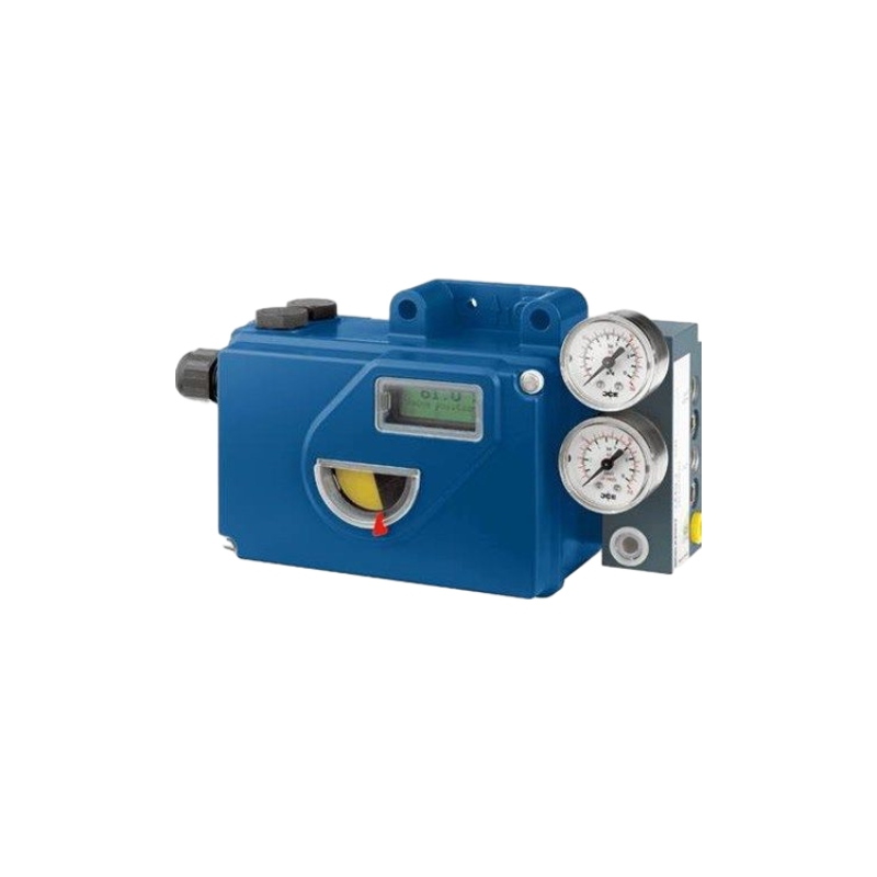
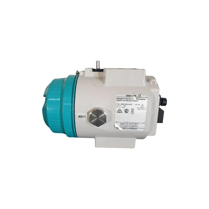
Advantages of SIPART PS2 positioners
- Simple installation and automatic commissioning (self-adjustment of zero and span)
- Simple operation with
- Local operation (manual operation) and configuration of the device using three buttons and a user-friendly two-line display
- Parameterization via SIMATIC PDM
- Very high-quality control thanks to an online adaptation procedure
- Negligible air consumption in stationary operation
- “Tight shut-off” function (ensures maximum positioning pressure on the valve seat)
- Numerous functions can be activated by simple configuring (e. g. characteristic curves and limits)
- Extensive diagnostic functions for valve and actuator
- Only one device version for linear and part-turn actuators
- Few moving parts, hence insensitive to vibrations
- External non-contacting position sensor as an option for extreme ambient conditions
- “Intelligent solenoid valve”: Partial Stroke Test and solenoid valve function in a single device
- Partial Stroke Test e. g. for safety valves
- Can also be operated with purified natural gas, carbon dioxide, nitrogen or noble gases
- SIL (Safety Integrity Level) 2
Application of SIPART PS2 positioners
- Chemical/petrochemical
- Power stations
- Paper and glass
- Water, waste water
- Food and pharmaceuticals
- Offshore plants
Specifications of SIPART PS2 positioners
| Basic electronics
without explosion protec- tion |
Basic electronics
with explosion protection Ex d |
Basic electronics
with explosion protection “ia” |
Basic electronics
with explosion protection “ic”, “ec”, “t” |
||
| Electrical specifications | |||||
| Current input IW
• Rated signal range • Test voltage • Binary input BIN1 (terminals 9/10; electri- cally connected to the basic device) |
0/4 … 20 mA 840 V DC, 1 s Suitable only for floating contact; max. contact load < 5 mA at 3 V |
||||
| 2-wire connection (terminals 6/8) 6DR50.. and 6DR53.. without HART 6DR51.. and 6DR52.. with HART | |||||
| Current to maintain the auxiliary power supply | ³ 3.6 mA | ||||
| Required load voltage UB (corresponds to
Ù at 20 mA) • Without HART (6DR50..) – Typical – Max. • Without HART (6DR53..) |
|||||
| 6.36 V (= 318 Ù)
6.48 V (= 324 Ù) |
6.36 V (= 318 Ù)
6.48 V (= 324 Ù) |
7.8 V (= 390 Ù)
8.3 V (= 415 Ù) |
7.8 V (= 390 Ù)
8.3 V (= 415 Ù) |
||
| – Typical
– Max. • With HART (6DR51..) – Typical – Max. • With HART (6DR52..) – Typical – Max. • Static destruction limit |
|||||
| 7.9 V (= 395 Ù)
8.4 V (= 420 Ù) |
–
– |
–
– |
–
– |
||
| 6.6 V (= 330 Ù) 6.6 V (= 330 Ù) –
6.72 V (= 336 Ù) 6.72 V (= 336 Ù) – |
–
– |
||||
| –
– ± 40 mA |
8.4 V (= 420 Ù)
8.8 V (= 440 Ù) ± 40 mA |
8.4 V (= 420 Ù)
8.8 V (= 440 Ù) – |
8.4 V (= 420 Ù)
8.8 V (= 440 Ù) – |
||
| Effective internal capacitance Ci
• Without HART • With HART |
|||||
| – – 11 nF
– – 11 nF |
“ic”: 11 nF
“ic”: 11 nF |
||||
| Effective internal inductance Li
• Without HART • With HART |
|||||
| –
– |
–
– |
209 µH
312 µH |
“ic”: 209 µH
“ic”: 312 µH “ic”: Ui = 30 V Ii = 100 mA “ec”/”t”: Un £ 30 V In £ 100 mA |
||
| For connecting to circuits with the follow- ing peak values | – | – | Ui = 30 V
Ii = 100 mA Pi = 1 W |
||
| 3-/4-wire connection (terminals 2/4 and 6/ 8)
6DR52.. with HART, explosion-proof 6DR53.. without HART, non-explosion- proof |
|||||
| Load voltage at 20 mA | £ 0.2 V (= 10 Ù) £ 0.2 V (= 10 Ù) £ 1 V (= 50 Ù) | £ 1 V (= 50 Ù) | |||
| Auxiliary power UAux | 18 … 35 V DC | 18 … 35 V DC | 18 … 30 V DC | 18 … 30 V DC | |
| Current consumption IH | (UAux -7.5 V)/2.4 kÙ [mA] | ||||
| Effective internal capacitance Ci | – | – | 22 nF | 22 nF
0.12 mH “ic”: Ui = 30 V Ii = 100 mA “ec”/”t”: Un £ 30 V In £ 100 mA Between UAux and IW |
|
| Effective internal inductance Li | – | – | 0.12 mH | ||
| For connecting to circuits with the follow- ing peak values | – | – | Ui = 30 V
Ii = 100 mA Pi = 1 W |
||
|
Electrical isolation |
Between UAux and IW |
Between UAux and IW |
Between UAux and IW (2 intrinsically safe circuits) |
||
| HART communication
HART version PC parameterization software |
7 SIMATIC PDM; supports all device objects. The software is not included in the scope of delivery. |
||||