I. Motor Protection Circuit Breaker (MPCB)
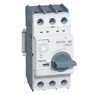
- Core Protection Functions
MPCB integrates three core protection functions: overload protection, short-circuit protection, and phase-failure protection, with some models capable of expanding earth fault protection. Its overload protection adopts the bimetallic strip thermal tripping principle, which can simulate the heating characteristics of the motor and prevent insulation aging caused by long-term motor overload.
The short-circuit protection is realized through an electromagnetic tripping mechanism, with a response time of ≤0.1s, which can quickly cut off the short-circuit current of 10In~100In and protect the motor windings from overcurrent impact.
- Selection and Parameter Setting
Rated Current (In): It shall match the motor rated current (Ie), usually taking 1.05Ie~1.2Ie (considering the motor starting current). For example, for a 15kW 380V motor (Ie≈30A), an MPCB with In=32A should be selected.
Tripping Characteristic: Priority shall be given to the “Class 10” tripping curve (overload tripping time: 10s~100s@6In), which is suitable for the starting characteristics of most squirrel-cage asynchronous motors and avoids false tripping during startup.
Breaking Capacity (Icu): It shall be selected according to the short-circuit current of the power distribution system. For example, if the short-circuit current of the end power distribution circuit is ≤5kA, an MPCB with Icu=6kA can meet the requirements.
- Installation and Application Requirements
It shall be installed vertically in the main circuit of the motor control cabinet, and the incoming and outgoing terminals shall be connected with copper bars or insulated wires of 16mm² or above to ensure the contact resistance is ≤50mΩ.
The wiring distance between MPCB and the motor should not exceed 50m to avoid false action of MPCB caused by line voltage drop; if the distance exceeds 50m, the rated current of MPCB shall be increased by 10%~15%.
Check the flexibility of the tripping mechanism regularly (quarterly); if jamming occurs, replace it immediately to prevent protection failure.
II. Advanced Motor Protection Relay

- Core Protection Functions
Compared with MPCB, the advanced motor protection relay has refined protection and intelligent monitoring capabilities. In addition to the basic overload, short-circuit, and phase-failure protection, it can also realize:
Locked-Rotor Protection: By detecting the sudden change of motor current (usually >8Ie), the circuit is cut off within 0.5s~2s to prevent winding burnout caused by motor rotor jamming.
Three-Phase Current Unbalance Protection: When the three-phase current difference is >15%, an alarm signal is sent and the circuit trips with a delay to prevent the motor from overheating due to single-phase operation.
Temperature Protection: It supports connecting PTC thermistors or RTDs (platinum resistors) to directly monitor the motor winding temperature (usually set at a threshold of 125℃) and realize “direct measurement” overheating protection.
Remote Monitoring: It is connected to the PLC or SCADA system through the RS485/Modbus protocol to upload real-time data such as motor current, temperature, and operating status, and supports remote reset and parameter modification.
- Selection and Parameter Setting
Current Range: Select a suitable current transformer (CT) according to the motor rated current. For example, for a motor with Ie=50A, match it with a 50/5A CT, and set the relay current input range to 0~5A.
Protection Threshold Setting: The locked-rotor current threshold is set to 8Ie~10Ie, the unbalance degree threshold is set to 10%~20% (adjusted according to the motor load characteristics), and the temperature threshold refers to the motor insulation class (Class A: 105℃, Class B: 130℃).
Auxiliary Power Supply: Priority shall be given to AC220V/DC24V dual power supply to ensure that fault records (storing at least 100 fault messages) can still be saved after power failure.
- Installation and Application Requirements
It shall be installed in the secondary circuit of the motor control cabinet and form a “secondary protection linkage” with MPCB and contactor: when the relay detects a fault, it first cuts off the contactor coil power supply, and then triggers MPCB tripping to avoid arc erosion of the main circuit.
Calibrate the current sampling accuracy through the panel or upper computer regularly (monthly), and the error shall be controlled within ±2%; if “false alarm” occurs, check whether the CT wiring is loose or the motor load is abnormal.
III. Motor Contactor
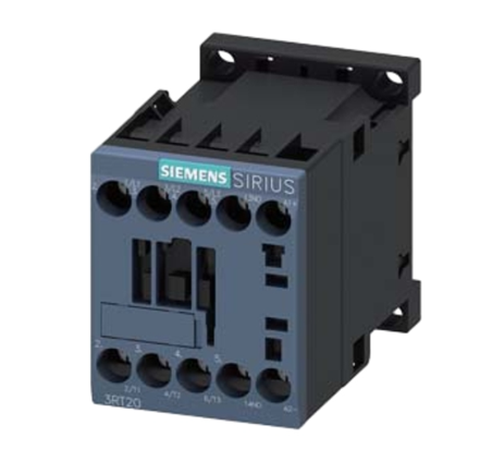
- Core Protection Auxiliary Functions
Although the contactor does not directly provide overload and short-circuit protection, its reliable on-off capability and arc-extinguishing performance are the “execution core” of the protection solution, and its main functions include:
Normal Start-Stop Control: The closing and opening of the main contacts are realized through the energization and de-energization of the coil to control the motor start and stop. The rated current of the main contacts shall be ≥1.5Ie (to adapt to the motor starting current).
Fault Breaking Coordination: When MPCB or the protection relay triggers protection, the contactor shall open the main contacts within 0.05s to cut off the motor power supply and avoid fault expansion.
Arc-Extinguishing Protection: A grid-type arc-extinguishing cover is adopted to extinguish the arc generated during breaking (when the breaking current is ≤10In, the arc extinguishing time is ≤0.02s), preventing contact erosion and phase-to-phase short circuit.
- Selection and Parameter Setting
Rated Operating Current (Ie): The rated current of the main contacts is ≥1.5Ie (motor rated current). For example, for a 22kW 380V motor (Ie≈44A), a contactor with Ie=63A should be selected.
Coil Voltage: It shall match the control circuit power supply, usually selecting AC220V (easy to connect to the municipal power supply) or DC24V (suitable for explosion-proof occasions). The coil pull-in voltage range shall meet 85%~110% of the rated voltage.
Auxiliary Contacts: At least 1 set of normally open auxiliary contacts (for self-locking control) and 1 set of normally closed auxiliary contacts (for fault interlock protection) shall be configured.
- Installation and Application Requirements
It shall be installed in the main circuit between MPCB and the motor, with a distance of ≥100mm from MPCB to avoid mutual influence of heat dissipation; a space of ≥50mm shall be reserved under the contactor to facilitate wiring and heat dissipation.
Check the wear of the main contacts regularly (semiannually); if the contact thickness is ≤1/2 of the original thickness or severe erosion occurs, replace them immediately; at the same time, clean the metal debris in the arc-extinguishing cover to prevent the reduction of phase-to-phase insulation.
For motors with frequent start-stop (start-stop >10 times per hour), “frequent operation type” contactors (rated operation times ≥1200 times per hour) shall be selected to extend the service life.
IV. Motor Fuse
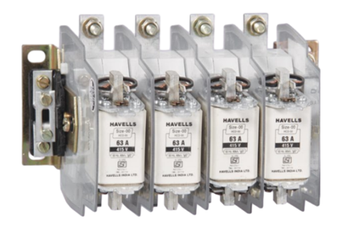
- Core Protection Functions
As the “last line of defense” for short-circuit protection, the fuse is mainly used to make up for the short-circuit protection blind areas of MPCB and contactors, and its core advantages are:
Fast Breaking Capacity: When an extremely large short-circuit current (>100In) occurs in the circuit, the fuse can blow within 5ms~10ms, which is much faster than the electromagnetic tripping time of MPCB (0.1s), and can effectively protect semiconductor devices (such as frequency converters) and motor windings.
Selective Protection: By selecting fuses with different fusing characteristics, “upper and lower level coordination” can be realized. For example, the upper-level fuse adopts the “gG” characteristic (full-range protection), and the lower-level fuse adopts the “aM” characteristic (motor-specific protection) to ensure that only the fault circuit is cut off during a fault without affecting other equipment.
- Selection and Parameter Setting
Fuse Element Rated Current (In): For directly started motors, In=1.25Ie~1.5Ie (to avoid fusing due to starting current); for motors with star-delta starting or soft starting, In=1.1Ie~1.2Ie is sufficient. For example, for an 11kW 380V motor (Ie≈22A), a fuse element with In=25A should be selected for direct starting.
Breaking Capacity (Icu): It shall be ≥ the expected short-circuit current of the power distribution system. For example, if the expected short-circuit current of the end circuit is ≤10kA, a fuse with Icu=12kA shall be selected.
Fusing Characteristic: Priority shall be given to “aM” type motor-specific fuses, which have a long overload fusing time (can withstand the starting current) and a short short-circuit fusing time (quickly breaks the fault), adapting to the load characteristics of the motor.
- Installation and Application Requirements
It shall be installed at the incoming end of MPCB or the outgoing end of the contactor, adopting a vertical installation method. The fuse element shall be in close contact with the fuse base to avoid local overheating caused by poor contact.
It is strictly forbidden to replace the fuse element with copper wire or iron wire, and only one fuse element can be installed in the same fuse (parallel connection is not allowed); when replacing the fuse element, the upper-level power supply shall be cut off first to avoid electric shock risks.
Cooperative Coordination Strategy of the Four Products
Normal Operation: The main contacts of the contactor are closed, MPCB provides basic overload protection, the advanced protection relay monitors the motor status in real time, and the fuse is in a standby state.
Overload Fault: If the motor is overloaded (1.2Ie~6Ie), the bimetallic strip of MPCB bends due to heat and trips within 10s~100s; at the same time, the advanced protection relay sends an overload alarm and records the fault information.
Locked-Rotor/Unbalance Fault: After the advanced protection relay detects the fault, it cuts off the contactor coil power supply within 0.5s, and the contactor opens the main circuit; if the contactor is stuck and not opened, MPCB trips to cut off the power supply within 10s.
Short-Circuit Fault: If a slight short circuit (10In~100In) occurs, the electromagnetic tripping mechanism of MPCB acts within 0.1s; if an extremely large short circuit (>100In) occurs, the fuse blows within 5ms to quickly cut off the fault circuit.
Through the above cooperative coordination, “graded protection, rapid response, and accurate positioning” can be realized, which maximizes the safe operation of low-voltage motors and reduces the fault downtime and maintenance costs.