In smart meter electricity metering applications, both primary and secondary current transformers (CTs) serve as essential metering components; their core function is to transform circuit currents to match the meter’s measurement range while ensuring metering safety and accuracy.
Significant differences exist between the two regarding installation location, current parameters, application scenarios, installation methods, and costs—factors that directly impact metering compatibility and the implementation of on-site retrofitting. This article will introduce current transformer differences from a practical user perspective to facilitate equipment selection and on-site installation.
Primary and secondary CT Difference between Definitions
What is Primary Current Transformer?
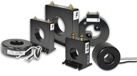
The primary current sensor is a fundamental metering transformer connected directly in series with or clamped onto the main power circuit; it serves as a primary-stage current conversion device within the power system. It interfaces directly with high-voltage, high-current main power lines and utilizes electromagnetic induction to convert the massive operating current of the main circuit into a standardized current suitable for metering by smart meters.
What is Secondary Current Transformer?
The secondary current sensor is an auxiliary miniature transformer that does not make direct contact with the main power circuit; instead, it is installed on the secondary output circuit of the primary current sensor. It takes the standardized current output from the primary sensor as its input to perform a refined secondary current conversion, ultimately outputting a low-level current signal to the smart meter; it functions as a secondary-stage signal conversion device within the metering system.
Primary and secondary CT Differences in Electrical Parameters
1. Differences in Input and Output Currents
Primary Current Transformation: The input is the actual high current from the main power circuit, covering a wide measurement range; the output is a standard nominal current (fixed at 1A or 5A) used in the power industry—a universal signal for power metering that is compatible with the vast majority of power equipment.
Secondary Current Transformation: The input is fixed at the standard output current of the primary transformer (1A/5A); the output is a low-level current in the milliampere range, specifically designed for high-precision sampling in smart meters to meet the small-signal acquisition requirements of internal measurement modules.
2. Differences in Transformation Ratio Adaptation
Primary Current Transformation: The transformation ratio is selected based on the actual load current of the main circuit on-site; it serves as the fundamental ratio for power metering and directly determines the overall measurement range.
Secondary Current Transformation: It does not have its own independent transformation ratio setting; the ratio parameters configured in on-site instruments or smart meters must match those of the primary transformer exactly. It merely scales the current signal proportionally without altering the fundamental metering ratio parameters, thereby ensuring the accuracy and alignment of metering data.
Primary and secondary CT Differences in Applications
1. Primary Current Transformer Applications
Primarily used in high-voltage, high-current AC power systems, these are the preferred choice for new power distribution projects and scenarios where distribution cabinets offer ample space. They are widely integrated with equipment such as circuit breakers, load-break switches, power protection devices, smart meters, and ammeters. Serving as independent, complete front-end metering and data acquisition units, they perform core functions including main-circuit current acquisition, metering, line protection, and power monitoring.
2. Secondary Current Transformer Applications
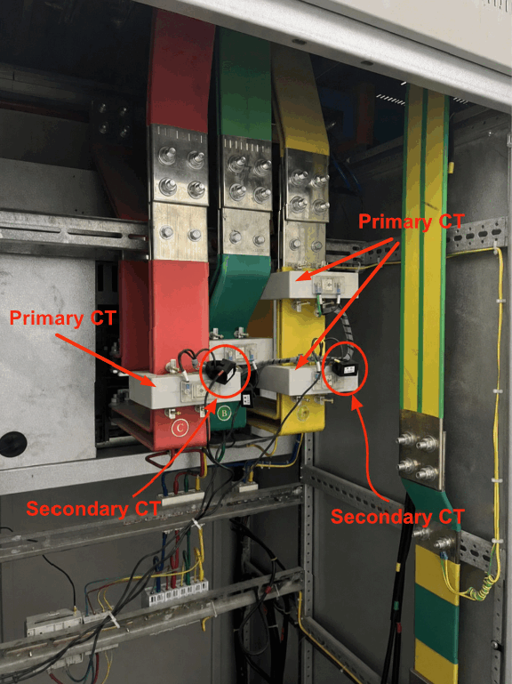
Designed primarily for the retrofitting of aging power distribution systems, scenarios with limited cabinet space, and situations where the main circuit cannot be dismantled. When a distribution cabinet is already equipped with a primary current transformer and dismantling the primary equipment is not feasible, these units can be directly clipped onto the secondary output leads of the existing transformer without altering the main circuit. Additionally, in high-current metering applications, they can replace large-specification primary current transformers, significantly reducing equipment procurement and installation costs.
Primary and secondary CT difference between installation and Advantages
- Primary-Side Sensing
Installation requires a power outage and direct connection to the main power circuit; the process is complex, the timeline is longer, and there are strict requirements regarding installation space. Its advantages include high equipment stability, strong interference immunity, and high metering accuracy. It is well-suited for long-term, stable operation in new power projects and supports both metering and line protection functions.
- Secondary-Side Sensing
This method supports retrofitting without disconnecting wires or cutting off power, offering convenient installation and high efficiency; there is no need to alter the original main circuit or primary transformer equipment. Compact in size and requiring minimal space, it is ideally suited for retrofitting legacy power distribution cabinets. Its core advantages are low cost, ease of retrofitting, and the fact that it does not affect the structure of the existing power distribution system.
Primary and secondary CT between Functional Positioning and Metering
1. Primary Instrument Transformer: The Core Metering Data Acquisition Unit
Serving as the initial checkpoint for power metering data acquisition, this unit performs the step-down conversion of high voltages and high currents. It determines the metering range and baseline accuracy of the electricity meter while also capturing signals for circuit overload and short-circuit protection. It is a fundamental component for metering, protection, and monitoring within power systems.
2. Secondary Instrument Transformer: The Metering Signal Adaptation Unit
This unit does not define measurement ranges or provide protection functions; instead, it acts solely as a signal adaptation device. It converts the standard current output from the primary transformer into low-level sampling signals that smart meters can accurately process. This resolves signal incompatibility issues between legacy equipment and modern smart meters, ensuring the accuracy and validity of metering data following system upgrades.
Conclusion
In short, the primary instrument transformer functions as the “primary acquisition device,” while the secondary instrument transformer serves as an “auxiliary adaptation device.” The primary transformer connects to the main power circuit to capture raw current; it is suitable for new installations and supports both metering and protection functions. The secondary transformer connects to the secondary circuit of the primary transformer to handle signal adaptation; it is primarily used for retrofitting legacy systems and low-cost installations.
Users can select the appropriate transformer type based on project requirements—such as whether it is a new installation or a retrofit—as well as available space in power distribution cabinets and load current levels. This targeted selection ensures smart meter accuracy and enhances power system reliability while effectively controlling construction and equipment costs.