What is the difference between a relay and a contactor?
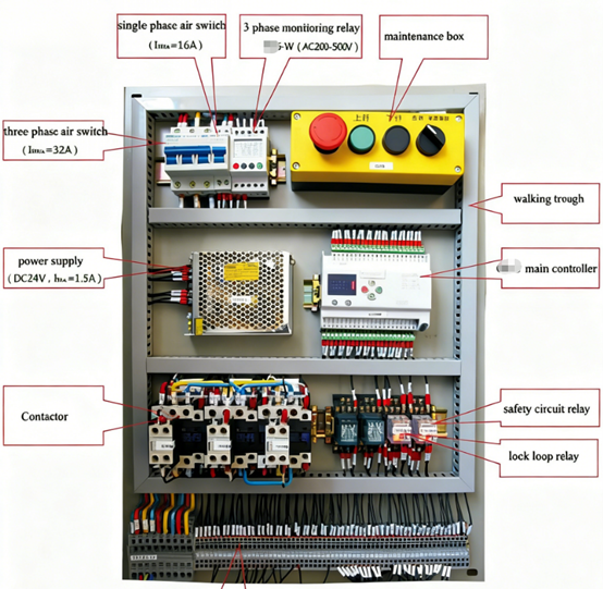
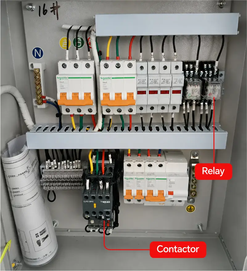
Relays and contactors are commonly found in the electrical cabinets of automation equipment. Both feature a coil; when the coil is energized, the internal contacts switch state. While they operate on similar principles, they are designed for different applications and cannot be arbitrarily interchanged. This article highlights the differences between the two.
What is a relay?
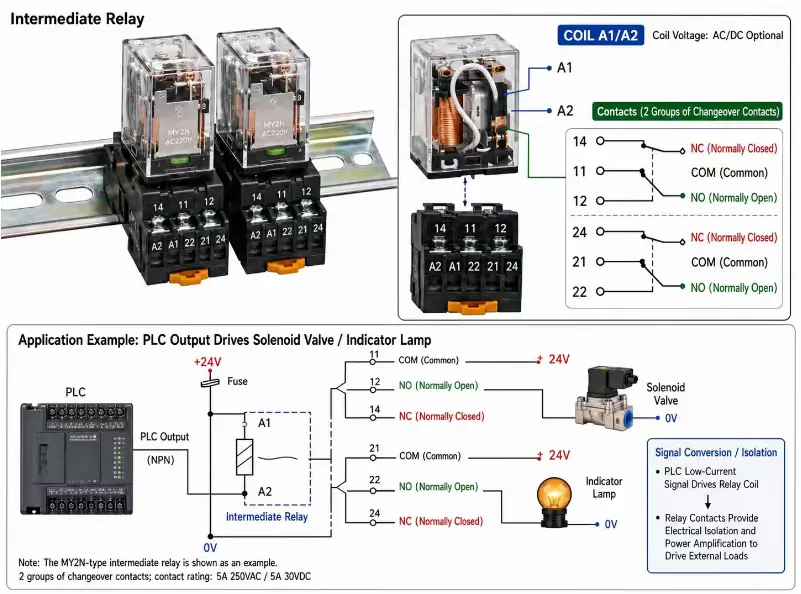
A relay is an electrical switching device that uses an electrical signal to control the making or breaking of another circuit; it typically consists of a coil and one or more sets of contacts. When the coil is energized, the resulting electromagnetic force actuates the contacts, enabling circuit control, isolation, or signal conversion. In automation control systems, relays are frequently used for PLC signal expansion, control signal conversion, electrical isolation, and the control of small loads.
What is a contactor?
A contactor is an electromagnetic switching device specifically designed for the frequent making and breaking of power loads; it is primarily composed of a coil, main contacts, and auxiliary contacts. It is commonly used to control loads such as motors, fans, pumps, heaters, and compressors. Unlike standard relays, contactors are engineered to handle high currents and frequent switching operations. They are equipped with arc-suppression mechanisms to enhance reliability and extend service life when switching high-power loads. There are AC contactors and DC contactors.
How do relays and contactors work?
Both relays and contactors operate by using a low-power signal to energize a coil. This generates a magnetic force that actuates the contacts (opening or closing them), thereby indirectly controlling the connection of an external circuit. The control logic follows this sequence: low-power signal → coil → contact actuation → load control. They are fundamental components in electrical control cabinets that enable “low-power signals to control high-power loads.” For example, consider a PLC outputting a 24V control signal. This signal is not suitable for directly driving a three-phase motor. Instead, it can be used to control an electromagnetic coil. Once energized, the coil generates a magnetic force that pulls the internal contacts together, ultimately completing the circuit for the load.
Key differences between relays and contactors
Relays (typically intermediate relays): Focused on signal switching Acting as a “signal relay station” within an electrical control cabinet, they are primarily used for PLC signal expansion, electrical isolation, signal conversion, contact multiplication, and driving small control circuits (such as solenoid valves and indicator lights). They are compact, feature multiple sets of normally open/normally closed contacts, and handle control circuit signals rather than high-power switching operations.
Contactors: Focused on switching high-power loads
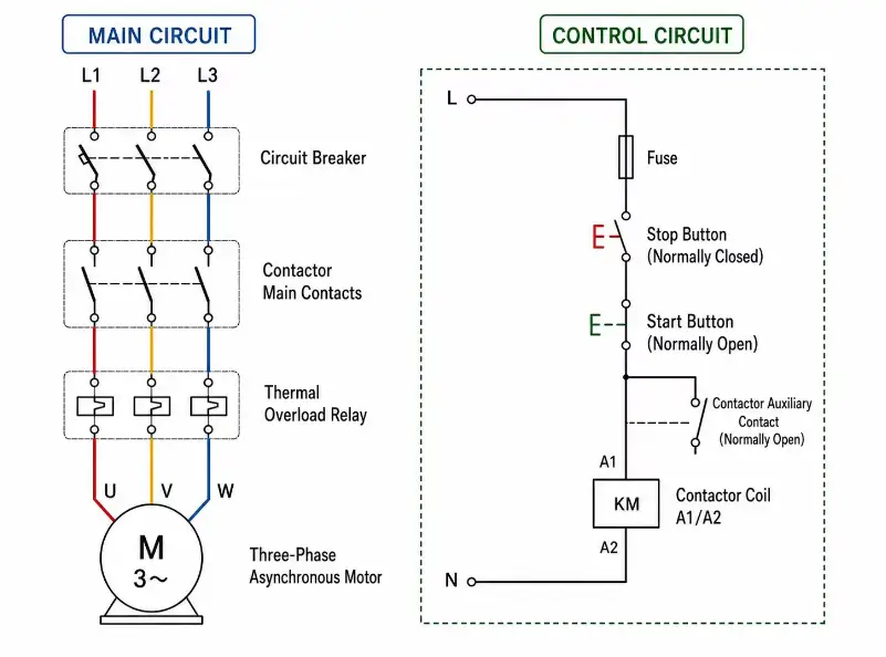
Designed specifically for high-power loads such as motors, heaters, fans, pumps, and compressors. Motors generate high inrush currents upon startup and arcs during disconnection; contactors are equipped with specialized arc-extinguishing structures to quench these arcs and reliably switch high currents. Three-phase contactors typically feature three sets of main contacts (L1-T1, L2-T2, L3-T3).
Note: It is an oversimplification to equate “relays” solely with low current and “contactors” solely with high current. Power relays and miniature contactors exist on the market; selection should be based on the specific operating conditions, not merely the rated current value.
How to choose between relays and contactors
If the application primarily involves PLC signals, state switching, contact expansion, or small control loads, a relay is usually the preferred choice. If the application requires frequent control of three-phase motors, high-power heating elements, fans, pumps, or other significant power loads, a contactor should generally be considered.
However, actual selection requires evaluating coil voltage, contact parameters, load characteristics, utilization category, operating frequency, electrical lifespan, and short-circuit/overload protection. For motor loads, it is particularly important to consider the device’s utilization category rather than simply comparing current ratings.