In online monitoring systems for partial discharge (PD) in power equipment, the installation location of the sensor directly determines the quality of signal acquisition and the accuracy of diagnosis. Even with high-performance monitoring equipment, an improper installation location can lead to severe signal attenuation, increased false alarm rates, or even missed fault detections.
Installation locations for PD sensors vary significantly depending on the type of power equipment and the detection principle employed. This article details the installation locations for High-Frequency Current Transformers (HFCTs), contact-type ultrasonic sensors, “three-in-one” PD sensors, and Ultra-High Frequency (UHF) sensors across various application scenarios.
Why is the installation location of PD sensors so critical?
Once a partial discharge occurs, it propagates outward in various forms, such as current pulses, electromagnetic waves, and ultrasonic waves. Different sensors detect different types of PD signals: HFCTs detect high-frequency pulse currents; UHF sensors detect ultra-high frequency electromagnetic waves; ultrasonic sensors detect mechanical vibration waves; and “three-in-one” sensors simultaneously detect Transient Earth Voltage (TEV), ultrasonic waves, and environmental parameters. Therefore, optimal detection results can only be achieved by installing the sensor at the location where the PD signal propagation is strongest.
Installation locations for High-Frequency Current Transformer (HFCT) PD sensors
HFCTs are primarily used to capture high-frequency pulse current signals generated by partial discharges. Installing PD sensors on cable terminations and intermediate joints
In high-voltage cable systems, PD signals typically propagate along the grounding wires. Therefore, HFCTs should be clamped directly onto the grounding wires of cable terminations or intermediate joints to effectively capture the PD pulse current signals.
Installation locations for main transformer PD sensors
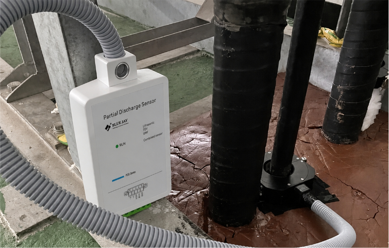
For transformer equipment, PD signals primarily propagate outward via the core grounding wire and the clamp grounding wire. Consequently, HFCTs should be installed on these grounding circuits. This method is widely used in online monitoring projects for equipment such as 110kV and 220kV main transformers and reactors.
Installation locations for contact-type ultrasonic sensors
Ultrasonic partial discharge (PD) sensors primarily detect mechanical vibration signals generated by partial discharges. For sealed equipment, the mounting location is critical.
Mounting locations for GIS equipment
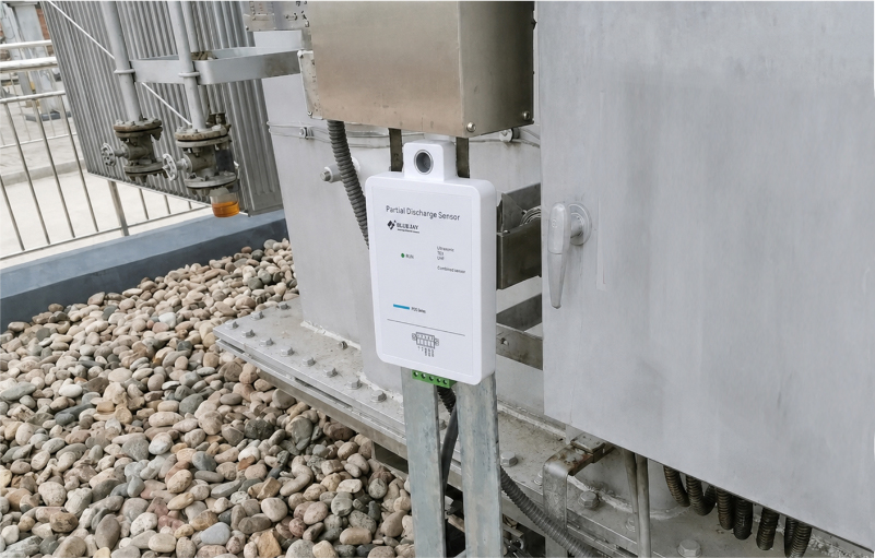
Ultrasonic waves generated by internal PD in GIS equipment must propagate through the metal enclosure to reach the outside. Therefore, the sensor should be mounted in direct contact with the GIS tank. Before installation, it is recommended to apply acoustic coupling grease and use a spring clamp to ensure proper contact pressure and eliminate air gaps. Depending on site conditions, the sensor can be secured using stainless steel cable ties, insulating straps, or hose clamps.
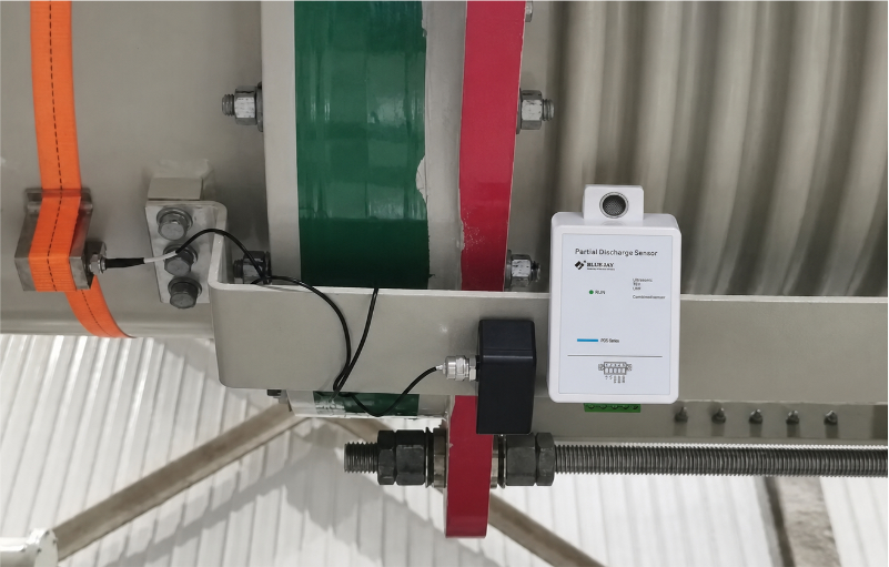
Mounting locations for gas-insulated switchgear (GIS/C-GIS)
The internal busbars of gas-insulated switchgear are located within an SF6 gas compartment. Since ultrasonic waves cannot directly penetrate the metal enclosure, a contact-based ultrasonic detection method is required. The installation principle is to select a location near the gas compartment—ideally close to the basin-type insulator—to ensure full contact with the tank.
Installation locations for “three-in-one” PD sensors
Three-in-one PD sensors integrate TEV (Transient Earth Voltage) detection, ultrasonic detection, and temperature/humidity monitoring. They are particularly suitable for the online monitoring of switchgear, ring main units (RMUs), and power distribution cabinets.
Installation of these sensors on switchgear should follow these principles: the TEV sensing surface must be attached directly to the metal panel of the cabinet, while the ultrasonic probe should be oriented toward areas where PD-generated sound waves are likely to escape, such as door gaps, ventilation vents, or cable compartment openings.
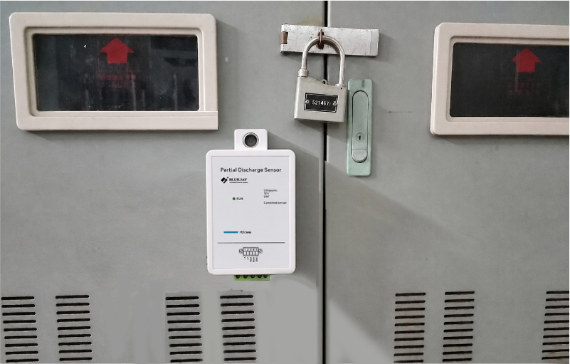
Installation locations for UHF Sensor
UHF partial discharge detection technology is characterized by strong interference immunity and high sensitivity, and it has currently become one of the mainstream technologies for the online monitoring of Gas-Insulated Switchgear (GIS).
1. Installation Locations for Switchgear Cabinets
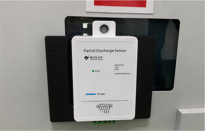
For switchgear equipment, UHF signals generated by partial discharge typically radiate outward through observation windows. Therefore, the following installation locations should be selected:
The central area of the observation window
The area near the busbar compartment
How do you choose the right partial discharge sensor?
| Equipment Type | Recommended Sensor | Recommended Installation Location |
| Main transformer | HFCT | Core grounding wire, clamping bracket grounding wire |
| Cable termination | HFCT | Grounding wire |
| GIS | UHF + Ultrasonic | Disc-type insulator, GIS enclosure |
| Switchgear | 3-in-1 + UHF | Observation window, switchgear cabinet door gaps |
| Ring Main Unit (RMU) | 3-in-1 | Cabinet surface and gap locations |
| Gas-insulated switchgear (GIS/C-GIS) | Ultrasonic + UHF | Gas compartment outer wall, disc-type insulator |
Conclusion
The installation location of partial discharge (PD) sensors is a critical factor influencing monitoring effectiveness. Optimal installation strategies depend on specific equipment configurations and PD signal propagation paths. In practical applications, the installation site should be selected by comprehensively considering the equipment type, sensor operating principles, and the on-site environment.
As a specialist manufacturer in the field of power equipment condition monitoring, Sell-Best offers a range of sensors—including HFCT (high-frequency current transformers), contact-type ultrasonic sensors, 3-in-1 PD sensors, and UHF sensors. These products are widely used in online partial discharge monitoring projects for equipment such as transformers, GIS, switchgear, and ring main units, providing reliable data to ensure the safe operation of power grid assets.