Arc flash reduction methods introduction
Arc flash reduction methods are a range of active and passive protection strategies used to safeguard people and equipment before an arc flash happens. Here are several common and effective ways to protect against arc flashes.
Arc flash reduction methods – Arc flash relay
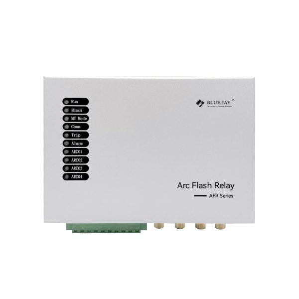
Real-time monitoring of arc light and current, achieving millisecond tripping, significantly reducing arc duration and energy.
- Detecting the strong light (usually using light sensors) and instantaneous overcurrent generated by the arc;
- The response speed is usually <1ms, significantly shortening the arc duration;
- Applicable to medium and low voltage systems, with obvious energy suppression effect.
Arc flash reduction methods – Upstream Fuse

Quickly cut off the power supply through high breaking capacity fuses to limit the energy of downstream fault arcs.
- When an arc fault occurs in the downstream equipment, the upper fuse acts quickly;
- Especially suitable for transformer secondary side or control circuit protection;
- Note that the fuse characteristics and coordination time need to be reasonably selected.
Maintenance mode Circuit Breaker
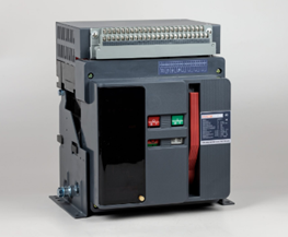
Lower the protection threshold in maintenance mode to achieve more sensitive tripping and improve personnel safety during maintenance.
- Commonly used in intelligent circuit breakers or digital protection devices;
- Activate this mode during maintenance to reduce the instantaneous protection setting value;
- The circuit breaker can trip faster in case of faults and reduce the arc duration;
- Usually with automatic exit, remote control and other functions.
Arc flash reduction methods – Zone interlocking
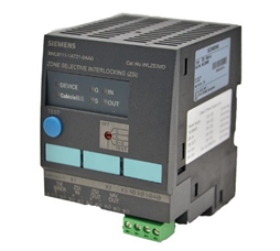
Link multiple protection devices to only trip the fault area, shorten the response time and avoid global power outage.
- When a fault occurs, only the device closest to the fault point is allowed to operate;
- Coordination between main/sub switches can be achieved to optimize the response time;
- Effectively reduce the energy and impact range of the arc occurrence area;
- Applicable to complex systems such as substations and low-voltage distribution rooms.
Arc flash reduction methods – Arc resistant switchgear board
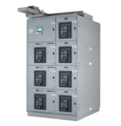
- Adopt arc resistant structure and ventilation design to effectively guide arc energy away from the operator.
- Reinforce the cabinet structure, close the arc channel, and guide the high-temperature gas to discharge upward;
- Provide better personnel protection and comply with standards such as IEEE C37.20.7 / IEC 62271-200;
- Although it cannot reduce arc energy, it can effectively limit its damage to operators;
- Commonly used in high-risk places or critical load areas.
| Method | Principle | Advantages | Typical Application |
| Arc Flash Relay | Light and current detection, ultra-fast tripping | Extremely fast response | Medium and low-voltage distribution |
| Upstream Fuse | Fast fuse operation | Simple and low cost | Control circuits, secondary protection |
| Maintenance Mode circuit breaker | Reduced trip thresholds during maintenance | Temporary high-sensitivity protection | During maintenance |
| Zone Interlocking | Coordinated protection device communication | Fast and selective response | Complex system zones |
| Arc-Resistant Switchgear | Arc-proof structural design | Strong personnel protection | High-voltage / critical areas |
Arc flash Reduction Methods Comparison
This part will compare arc flash reduction methods from selective coordination maintained, universal external connection, integral self test system, No Added Floor space, Digital Inputs, and Evaluates light & current.
| Arc flash Reduction Methods | selective coordination maintained | universal external connection | integral self test system | No Added Floor space | Digital Inputs | Evaluates light & current |
| Arc flash relay | Yes | Yes | Yes | Yes | Yes | Yes |
| Upstream fuse | No | Yes | No | No | No | No |
| Maintenance mode circuit breaker | Yes | No | No | Yes | No | No |
| Zone Interlocking | Yes | No | Yes | Yes | No | No |
| Arc resistant switchgear | Yes | No | No | No | No | No |
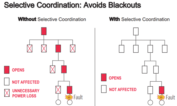
Selective coordination maintained
Selective coordination is defined as: the localization of an overcurrent condition to restrict outages to the circuit or equipment affected, accomplished by the selection and installation of overcurrent protective devices and their ratings or settings for the full range of available overcurrent, from overload to the available fault current, and for the full range of overcurrent protective device opening times associated with those overcurrents.
Selective coordination can reduce arc flash risks by localizing faults, preventing upstream tripping, protecting personnel and equipment, supporting fast protection devices, and improving system uptime.
2. Universal external connection
Universal external connection enhances arc protection by enabling fast integration with breakers, PLCs, and SCADA via standard interfaces. It improves response speed, shortens arc duration, and supports coordinated protection. Additionally, it boosts system compatibility and scalability, while allowing remote monitoring to reduce human error and enhance reliability.
3. Integral self-test system
Integrated self-test systems improve arc flash protection by automatically detecting faults in sensors, inputs, and outputs. This ensures timely maintenance and faster response to arc events, minimizing arc duration and energy. Without self-testing, manual checks may miss issues, increasing the risk of protection failure and reducing system reliability.
4. No Added Floor space
No additional space is required, which means that arc protection equipment (such as arc protection relays) can be directly installed in existing switch cabinets or distribution cabinets without expanding the equipment volume or re-layout. In this way, arc protection function can be realized without changing the original system structure, which is convenient for rapid deployment in space-constrained or renovation projects and improves system safety. At the same time, it also reduces installation costs and complexity, making key protection measures easier to promote and implement.
5. Digital Inputs
Digital inputs improve arc flash protection by providing fast, accurate, and noise-resistant signal processing, enabling quicker relay response to faults. This reduces arc duration and energy, enhancing safety and system reliability.
6. Evaluates light & current
The system uses arc protection relays that can evaluate both light and current (such as Bluejay’s 4-channel AFR-4 arc protection relay) to more comprehensively monitor the status of the electrical system. The generation of arcs is usually accompanied by abnormal changes in light and current. By detecting these two parameters at the same time, the occurrence and development of arcs can be more accurately judged to cut off the fault in time to protect the safety of equipment and personnel.
Conclusion
Arc reduction methods can achieve effective protection through systematic protection, covering active detection and rapid disconnection (such as arc relays, upper fuses), state identification (such as digital input, photoelectric detection), operation optimization (such as selective coordination, regional interlocking, maintenance mode), system integration (such as universal external connection, self-test) and structural protection (such as arc-resistant switchgear). The coordinated application of these technologies can shorten the arc duration, reduce energy release, improve fault response and system reliability, and provide comprehensive protection, especially for arc risk control in medium and low voltage power distribution, substations and important load areas.