Function introduction
-. Ground Fault Detection
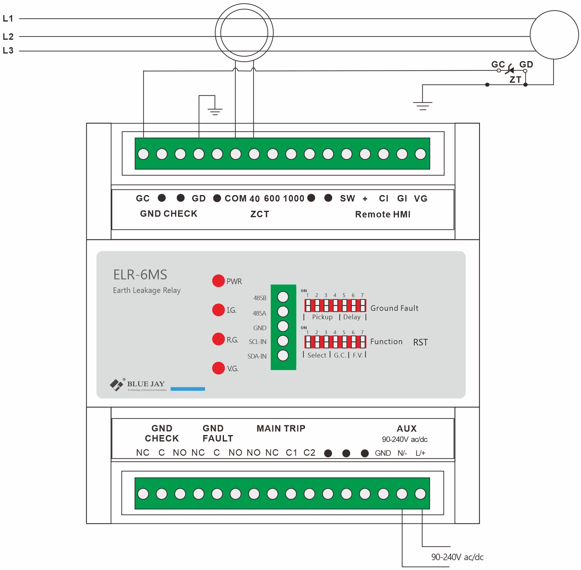
Ground fault detection requires the use of current sensors, and the ELR-6MS is designed to operate with current sensors with ratios of 1000:1, 600:1 and 40:1 (200:5).
-. Ground Check Detection
Ground check is achieved using a pilot wire (GC). This wire is usually a part of the power cable. It is used to carry monitoring current to the machine being monitored. The pilot wire must be properly terminated at its end point (the machine being monitored). A Zener diode terminator is required. This terminating diode is standard throughout the industry. It has two terminals marked GC and GD. The GC terminal is connected to the pilot wire inside the mobile equipment enclosure. The GD terminal is connected to the frame ground of the mobile equipment.
The purpose of the diode is to allow the ground fault relay to determine if the ground loop has been shorted. A shorted ground loop would appear as normal loop impedance if this were allowed to happen, while in fact, the mobile equipment may be completely ungrounded. Loss of zener voltage therefore causes the TRIP relay to operate and disconnect the power.
Specification
| Parameter | Value | |
| Normal voltage | 90-240 Vac/dc, 50/60 Hz
Power: 5VA AC or 5W DC |
|
| Ground fault | Range: 10-500mA
Delay range: instant – 10 seconds |
|
| Zero sequence sensors | Ratios supported 1000:1, 600:1 and 40:1 | |
| Ground check resistance | Range: 10 – 50Ohms, ±15%
Trip delay: 150ms, ±0.1% |
|
| Output contacts (3 DO) | Main trip relay | DPDT
Load capacity: 8A@250Vac, 8A@30Vdc |
| Auxiliary ground fault relay | SPDT
Load capacity: 16A@250Vac, 16A@30Vdc |
|
| Auxiliary ground check relay | SPDT
Load capacity: 16A@250Vac, 16A@30Vdc |
|
| Dielectric | Relay contacts to chassis – 1500Vrms for 1 minute
Control terminals to chassis – 1500Vrms for 1 minute |
|
| Temperature range | Operating temperature: -40°C to +60°C
Storage temperature: -40°C to +80°C |
|
| Dimensions | Standard 35mm Din-rail mounting
W*H*D: 108*110*66mm |
|
Wiring method