Features
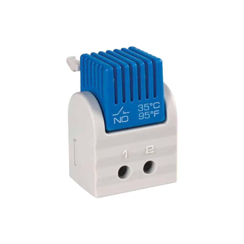
- Safe wiring with Push-In terminals
- Faster and tool-free wiring
- Improved air intakes for ventilation
- Easy adjustability of switch temperature setting
- for use in up to 5,000 m altitude
Specification
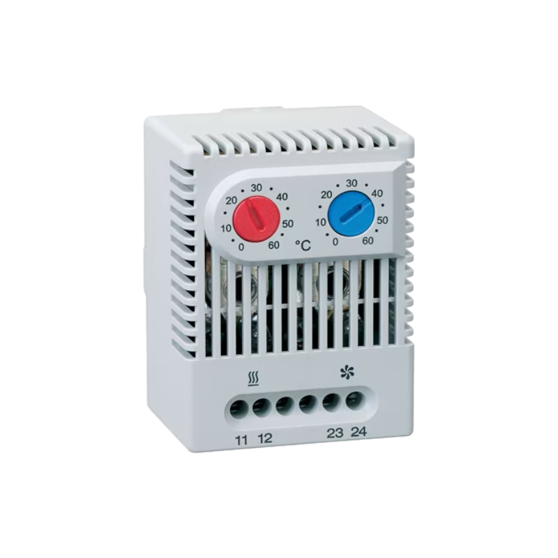
| Switching difference | 12.6 °F ±7 °F tolerance (7 K ±4 K) |
|---|---|
| Sensor element | thermostatic bimetal |
| Contact type | snap-action contact |
| Service life | 100,000 cycles verified |
| Max. operating voltage, frequency range | AC 250 V, 50-60 Hz |
| Max. inrush current | AC 16 A for 10 sec. |
| Connection1 | 2 Push-In clamps rigid wire 2.5 mm² (AWG 14) stranded wire 1.5 mm² (AWG 14) |
| Housing | plastic, UL 94V-0, light grey |
| Mounting | clip for 35 mm DIN rail, EN 60715 |
| Dimensions | 2.4 x 1.3 x 1.6″ (60 x 33 x 41 mm) |
| Weight | approx. 1.4 oz. (40 g) |
| Mounting position | variable |
| Operating/Storage temperature | -49 to +176 °F (-45 to +80 °C) |
| Operating/Storage humidity | max. 90 % RH (non-condensing) |
| Protection type/Protection class | IP20 / II |
| Overvoltage category/Altitude | II: up to 5,000 m; III: up to 2,000 m |
1 Stripped length of rigid wire: 0.4 to 0.5″ (10-12 mm). When connecting with wires, wire end ferrules must be used (square or trapezoid crimp). Length of wire end ferrule: 0.4″ or 0.5″ (10 or 12 mm).
Important note: The contact system of the regulator is subjected to environmental influences, thus the contact resistance may change. This can lead to a voltage drop and / or self-heating of the contacts.
| Setting range | Part No. (NC) |
Part No. (NO) |
Switching current²/ AC 250 V |
capacity AC 120 V |
max. DC 24-72 V |
Approvals | ||
|---|---|---|---|---|---|---|---|---|
| +32 to +140 °F | 11100.9-00 | 11101.9-00 | 10 (2) A | 15 (2) A | 30 W | VDE | UL File No. E164102 | EAC |
| +14 to +122 °F | 11100.9-01 | 11101.9-01 | 10 (2) A | 15 (2) A | 30 W | VDE | UL File No. E164102 | EAC |
| 0 to +60 °C | 11100.0-00 | 11101.0-00 | 10 (2) A | 15 (2) A | 30 W | VDE | UL File No. E164102 | EAC |
| -10 to +50 °C | 11100.0-01 | 11101.0-01 | 10 (2) A | 15 (2) A | 30 W | VDE | UL File No. E164102 | EAC |
| +20 to +80 °C | 11100.0-02 | 11101.0-02 | 3 (2) A | 3 (2) A | 30 W | VDE | UL File No. E164102 | EAC |
2 The level of switching current has an influence on the tolerance accuracy;