Features of Masibus Current Transducer
- High accuracy class of 0.2
- Complies with IEC 60688 standards
- Utilizes True RMS measurement
- Offers long-range, site-configurable inputs and outputs
- Allows on-site selection of output type (DC current or DC voltage)
- Maintains load-independent accuracy on all outputs
- Available in both single and dual output configurations
- Features a programming port for easy configuration
- Ensures fast response times
- Demonstrates excellent long-term stability
- Provides strong isolation and impulse resistance
- Includes transient protection
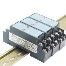
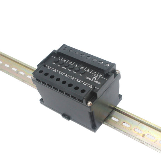
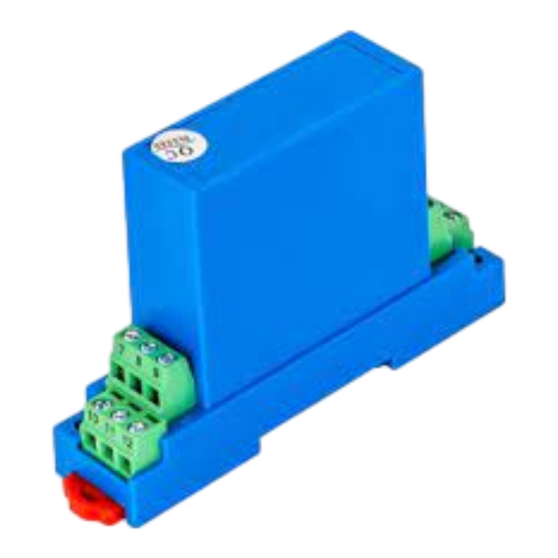
- Designed for DIN-Rail mounting for convenient installation.
Applications of Masibus Current Transducer
- Power generation and transmission distribution stations
- Building management
- Load dispatch centers
- Original Equipment Manufacturers (OEMs) for power equipment
- High-Tension (HT) and Low-Tension (LT) panels
- Substation automation
- Supervisory Control and Data Acquisition (SCADA)
- Local and central monitoring systems
Specification of Masibus Current Transducer
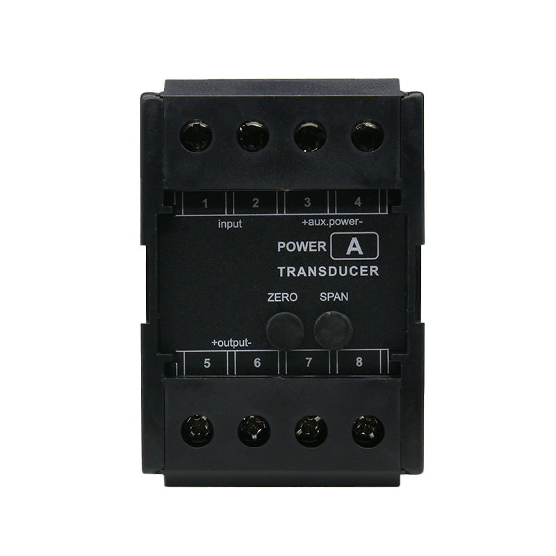
| Configuration | Single phase | Auxiliary Power Supply | |
| Input | Universal aux. supply : 85-265VAC, 50/60Hz or 100-300VDC
Power Supply Burden : < 5.5VA (2.2W) DC aux. Supply : 20-60VDC Burden : < 2.2W |
||
| AC Voltage | |||
| Nominal Input (Un) 57.7 V to 415 V
(PT Secondary) |
|||
| Measuring Voltage Range | 0 to 130 % Un | ||
| Measurement Method True RMS | Isolation (Withstanding Voltage)
Between primary terminals* and secondary terminals**: At least 3000 V AC for 1 minute Between primary terminals*: At least 3000 V AC for 1 minute Between secondary terminals**: At least 500 V AC for 1 minute * Primary terminals indicate aux power terminals & input terminals. ** Secondary terminals indicate analog O/P-1 and analog O/P-2. Insulation resistance: 200MΩ or more at 500 V DC between Input/Output/Power/ Case and grounding terminal |
||
| Burden | <0.3VA at Un | ||
| PT Ratio 1 to 9999.999 programmable on site | |||
|
Maximum Overload Voltage |
1.3 x Un continuously
2 x Un for 1 s, with up to 10 repetitions at 10 s intervals |
||
| AC Current | Environmental | ||
| Nominal Input (In)
(CT Secondary) |
1A to 5A | Operating Temperature | 0 to +55 C |
| Storage Temperature -40º to 85ºC | |||
| Measuring Current Range 0 to 150 % In | Relative Humidity | 25-95% non-condensing | |
| Measurement Method | True RMS | Warm up Time 15 minutes | |
| Burden <0.2VA at In | Installation Category | CAT III for < 300V AC | |
| CT Ratio | 1 to 9999.999 programmable on site | Protection Class II | |
| 2 x In continuously
Maximum Overload Current 20 x In for 1 s, with up to 10 repetitions at 100 s intervals |
Pollution Degree | 2 | |
| Ingress Protection Housing : IP40, terminals : IP20 | |||
| Mechanical | |||
| Frequency | 45 to 65Hz | Mounting Type | DIN-Rail |
| Analogue output | Dimension (in mm) 71H x 61W x 112D | ||
| Accuracy Class | 0.2 | Case Material | ABS |
| No. of Outputs 2 | Weight 0.4 Kg | ||
| Output Type | 4-20mA, 0-20mA, 0-10V, 0-5V, 1-5V DC | Connector Type | Metal screw |
| Maximum Load Resistance ≤750 Ω for 20 mA, ≥ 2 k Ω for 10 V
(for each output) |
Conductor Size for Terminals ≤ 4 mm2 | ||
| Communication Ports | |||
| Response Time | <500mS | Mini USB type: For on-site con | figuration |
| Ripple <0.4% peak to peak | Configuration Software Tool | ||
| Usage Group | I | mMFT
For on-site configuration of measurement inputs, output and online parameter reading. It can be freely downloaded from www.masibus.com |
|
| Standards compliance | |||
| Standards Accuracy as per IEC 60688 | |||