Feature of UBZ-302
- poor quality supply voltage (unacceptable voltage surges, phase loss, incorrect phase sequence and phase coincidence, phase/line voltage imbalance);
- mechanical overloads (symmetrical phase/line current overload);
- exceeding the negative sequence current threshold;
- phase current imbalance without overload, induced by the insulation fault inside the motor and/or the lead cable (the current imbalance factor is compared to the voltage imbalance factor using negative sequence);
- loss of motor torque (“dry stroke” for pumps) – protection based on the minimal starting and/or operating current;
- delayed motor start or rotor locking;
- abnormally low insulation level between the fixed coil and frame (testing before motor startup);
- ground fault of the stator coil during operation – protection against ground leakage current;
- motor thermal overload;
- coil overheating (measuring the coil temperature with integrated temperature sensors, or the body temperature with external temperature sensors).
Specification of UBZ-302
| Rated supply voltage: three-phase | 380/415V |
| Mains frequency, Hz | 48-62 |
| Rated currents range (when using integrated current transformers), A | 5-63 |
| Voltage hysteresis, (phase/line), V | 10/17 |
| Thermal hysteresis, % of accumulated heat at shutdown | 33 |
| Current tripping threshold detection accuracy, % of rated current, ≤ | 2 |
| Voltage tripping threshold detection accuracy, V, at least | 3 |
| Voltage based phase imbalance detection accuracy, V, at least | 3 |
| Minimum operational voltage:
– single-phase voltage power supply, with connected neutral wire, V, at least – three-phase power supply voltage, V, no more than |
180
450 |
| Main outputs
– load relay –two groups of changeover contacts for motor starter control – 8A, 250V at cos φ=1; – functional relay – one group of changeover contacts – 16A, 250Vat cos φ=1 (relay function assigned by the user) |
|
| Analog inputs
– two analog inputs for temperature sensors (type Pt100, Ni100,Ni120) – analog input for sensor with 0-10 V output – analog input for sensor with 4 mA (0mA) – 20 mA output – three analog inputs for standard CT with 5A output (type T-0.66 or similar) – input for differential current transformer (zero sequence transformer) |
|
| Temperature sensor resolution, °С | 1 |
| Power consumption (under load), VA, no more than | 5.0 |
| Weight, kg, no more than | 0.5 |
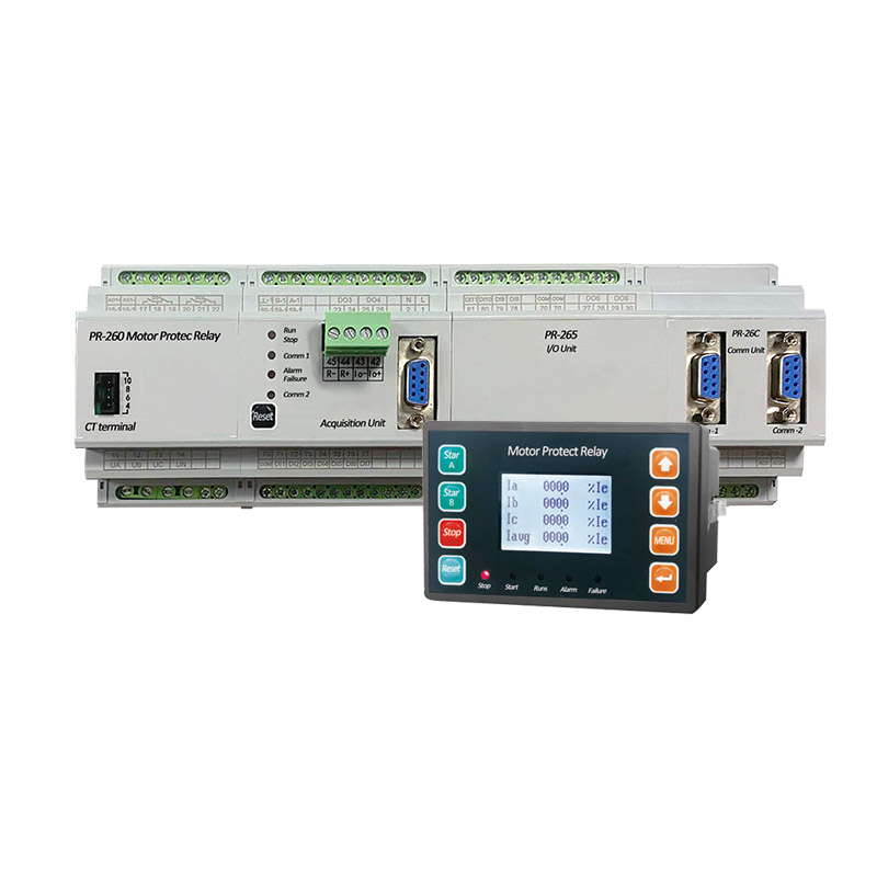
| Dimensions (figure 1.1) -nine S type modules
Mounting – on a standard 35 mm DIN bar Mounting position – any |
|