The rectifier working principle is to use the unidirectional conductive characteristics of semiconductor devices (such as diodes or thyristors) to convert the periodic changes of alternating current into unidirectional pulsating direct current. This article will introduce some common rectifier working principles from half-wave rectifiers, full-wave rectifiers, silicon-controlled rectifiers, and bridge rectifiers.
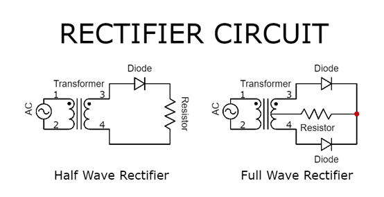
1. Working Principle of Half-Wave Rectifier
Overview: A half-wave rectifier is the simplest type of rectifier, using a single diode to convert AC to DC. It allows current to pass through during only one half of the AC cycle (positive or negative), effectively blocking the other half.
Components:
One diode
AC power source
Load resistor
Working Principle:
Positive Half-Cycle: During the positive half-cycle of the AC input, the diode is forward-biased (conducting), allowing current to pass through to the load resistor. This results in a positive voltage across the load.
Negative Half-Cycle: During the negative half-cycle, the diode is reverse-biased (non-conducting), blocking current flow. Consequently, no current reaches the load, and the voltage across the load is zero.
Output: The output voltage of a half-wave rectifier is a pulsating DC signal that occurs only during the positive half-cycles of the AC input. The resulting waveform has a frequency equal to that of the AC input but contains only positive values.
2. Working Principle of Full-Wave Rectifier
Overview: A full-wave rectifier converts both halves of the AC cycle into DC, resulting in a more efficient and smoother DC output than a half-wave rectifier. There are two common types: center-tap and bridge rectifiers.
Center-Tap Full-Wave Rectifier:
Components:
Center-tapped transformer
Two diodes
Load resistor
Working Principle:
Positive Half-Cycle: During the positive half-cycle, one diode is forward-biased, allowing current to pass through one-half of the transformer winding to the load.
Negative Half-Cycle: During the negative half-cycle, the other diode is forward-biased, allowing current to pass through the other half of the transformer winding to the load.
Output: The output voltage is a pulsating DC signal that occurs during both the positive and negative half-cycles of the AC input, resulting in a higher frequency output than the half-wave rectifier.
Bridge Rectifier:
Components:
Four diodes arranged in a bridge configuration
Load resistor
Working Principle:
Positive Half-Cycle: During the positive half-cycle, two diodes are forward-biased, allowing current to pass through the load resistor.
Negative Half-Cycle: During the negative half-cycle, the other two diodes are forward-biased, allowing current to pass through the load resistor in the same direction as during the positive half-cycle.
Output: The bridge rectifier also provides a pulsating DC output during both half-cycles of the AC input, similar to the center-tap full-wave rectifier, but without the need for a center-tapped transformer.
3. Working Principle of Silicon Controlled Rectifier (SCR)
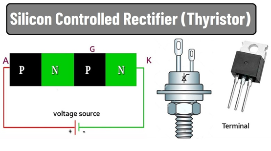
Overview: An SCR is a type of controlled rectifier that can switch and control high voltages and currents. It has three terminals: anode, cathode, and gate. The SCR can be triggered into conduction by applying a small gate current.
Components:
Anode
Cathode
Gate
Working Principle:
Forward Blocking Mode: When a positive voltage is applied to the anode with respect to the cathode, the SCR remains non-conductive (off) until a gate pulse is applied.
Forward Conduction Mode: Applying a positive gate pulse triggers the SCR into conduction, allowing current to flow from the anode to the cathode. The SCR remains in this conductive state even if the gate pulse is removed, as long as the anode-cathode voltage is positive.
Reverse Blocking Mode: When the voltage is reversed, the SCR remains non-conductive, blocking current flow.
Applications: SCRs are used in applications where control over the output voltage or current is required, such as in variable speed drives, controlled power supplies, and industrial motor controls.
4. Working Principle of Bridge Rectifier
Overview: A bridge rectifier uses four diodes arranged in a bridge configuration to convert both halves of the AC cycle into DC. This configuration eliminates the need for a center-tapped transformer.
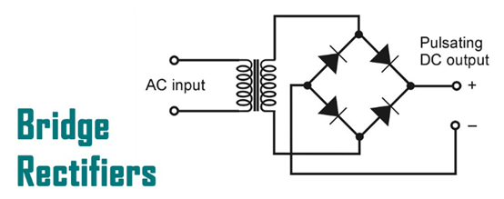
Components:
Four diodes
Load resistor
Working Principle:
Positive Half-Cycle: During the positive half-cycle of the AC input, two diagonally opposite diodes (say D1 and D2) are forward-biased, allowing current to flow through the load resistor.
Negative Half-Cycle: During the negative half-cycle, the other two diodes (D3 and D4) are forward-biased, allowing current to flow through the load resistor in the same direction as during the positive half-cycle.
Output: The bridge rectifier provides a pulsating DC output during both the positive and negative half-cycles of the AC input. This results in a smoother DC output compared to a half-wave rectifier.
Conclusion
Rectifiers are crucial components in converting AC to DC, with various types tailored to different applications. The half-wave rectifier is simple but less efficient, while the full-wave rectifier, including center-tap and bridge configurations, offers improved performance. Silicon-controlled rectifiers provide additional control for high-power applications. Understanding the working principles of these rectifiers helps in selecting the appropriate type for specific applications, ensuring efficient and reliable operation of electronic and electrical systems.