Voltage transformer wiring configurations vary depending on the system voltage level, neutral-point grounding method, and measurement requirements. Selecting the appropriate connection method is essential for accurate voltage measurement, reliable protection, and safe and stable power system operation. This article introduces several common voltage transformer wiring configurations and their typical applications.
Wiring of single-phase voltage transformers
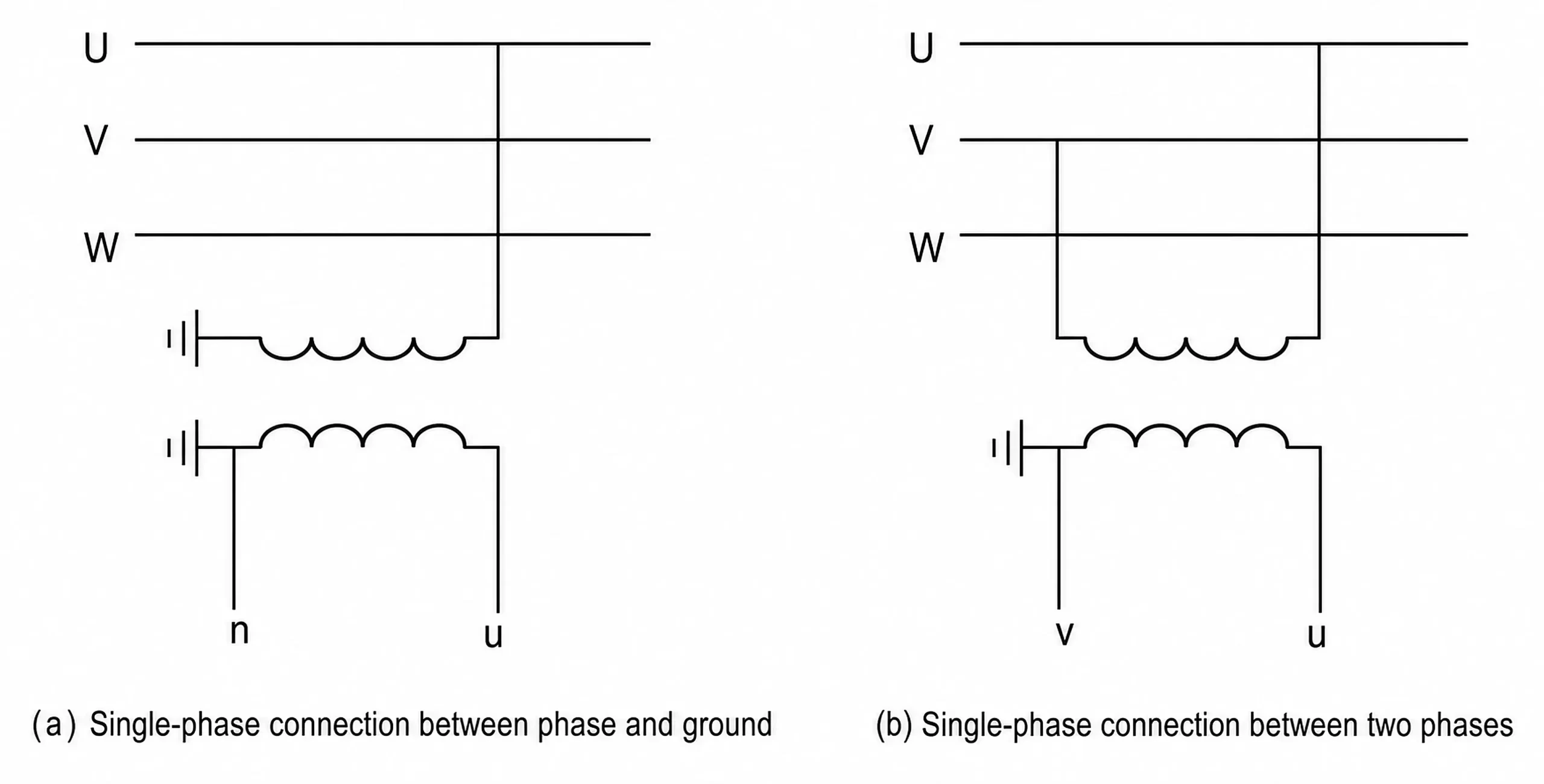
Figure (a) illustrates a single-phase voltage transformer with its primary winding connected between a phase and ground; this configuration is suitable for 110–220 kV systems with directly grounded neutral points and is used to measure phase-to-ground voltage.
This type of single-phase connection is commonly used in systems with high earth-fault currents to determine the absence of voltage and facilitate synchronization checks; while it can be connected to any phase, the corresponding phase of the busbar voltage must be used for the comparison criterion on the other side.
Figure (b) illustrates a single-phase voltage transformer with its primary winding connected between phases; this configuration is suitable for 3–35 kV systems with ungrounded neutral points and is used to measure line-to-line voltage. With this connection method, the primary side of the voltage transformer is not grounded, and one terminal of the secondary winding is grounded; however, no fuse is installed on the grounded terminal of the secondary winding.
V-V connection using two single-phase voltage transformers
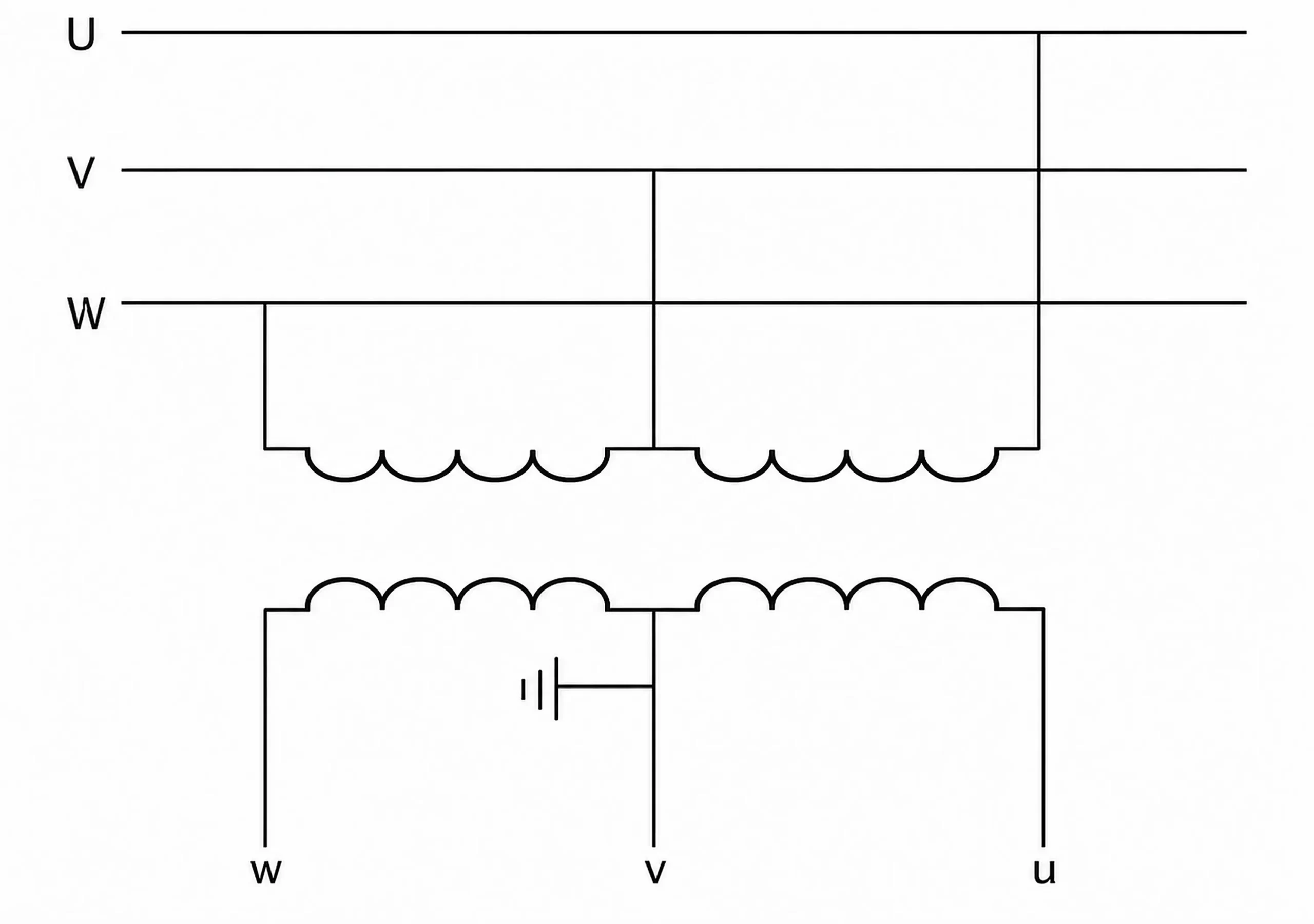
The figure illustrates a V-V connection configuration formed by two single-phase voltage transformers, which are connected across phases UV and VW, respectively. With this configuration, the primary windings of the transformers cannot be grounded, whereas the V-phase of the secondary windings is grounded. The V-V connection is suitable for power grids where the neutral point is either ungrounded or grounded via an arc-suppression coil; this setup allows for the measurement of line voltages but not phase voltages.
When configuring a V-V connection using two single-phase transformers, strict attention must be paid to transformer polarity; improper connection will prevent the formation of a valid V-V connection.
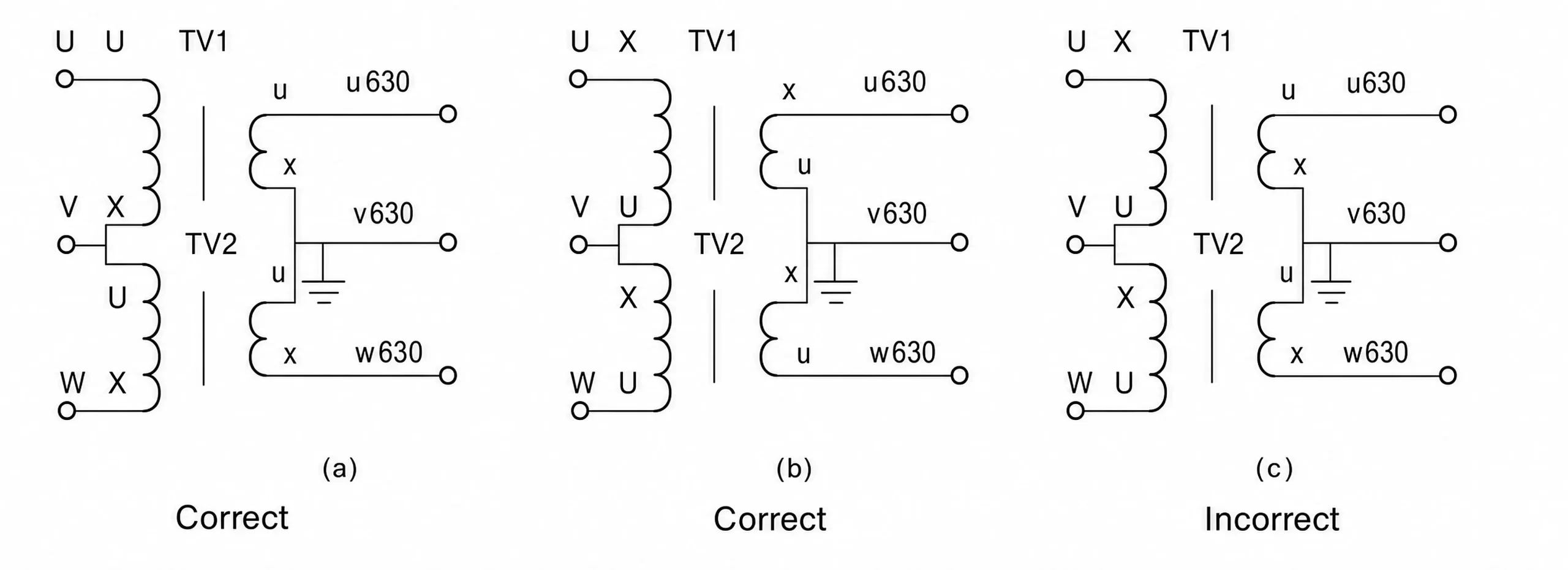
YNynd0 connection using three single-phase voltage transformers
The figure illustrates a YNynd0 connection configuration using three single-phase voltage transformers. The primary windings and main secondary windings are connected in a wye (star) configuration with the neutral point directly grounded, while the main secondary windings also provide a neutral connection to form an open-delta arrangement; this configuration enables the measurement of phase-to-ground voltage, phase-to-phase voltage, and zero-sequence voltage.
Wiring of three-phase, three-limb voltage transformers
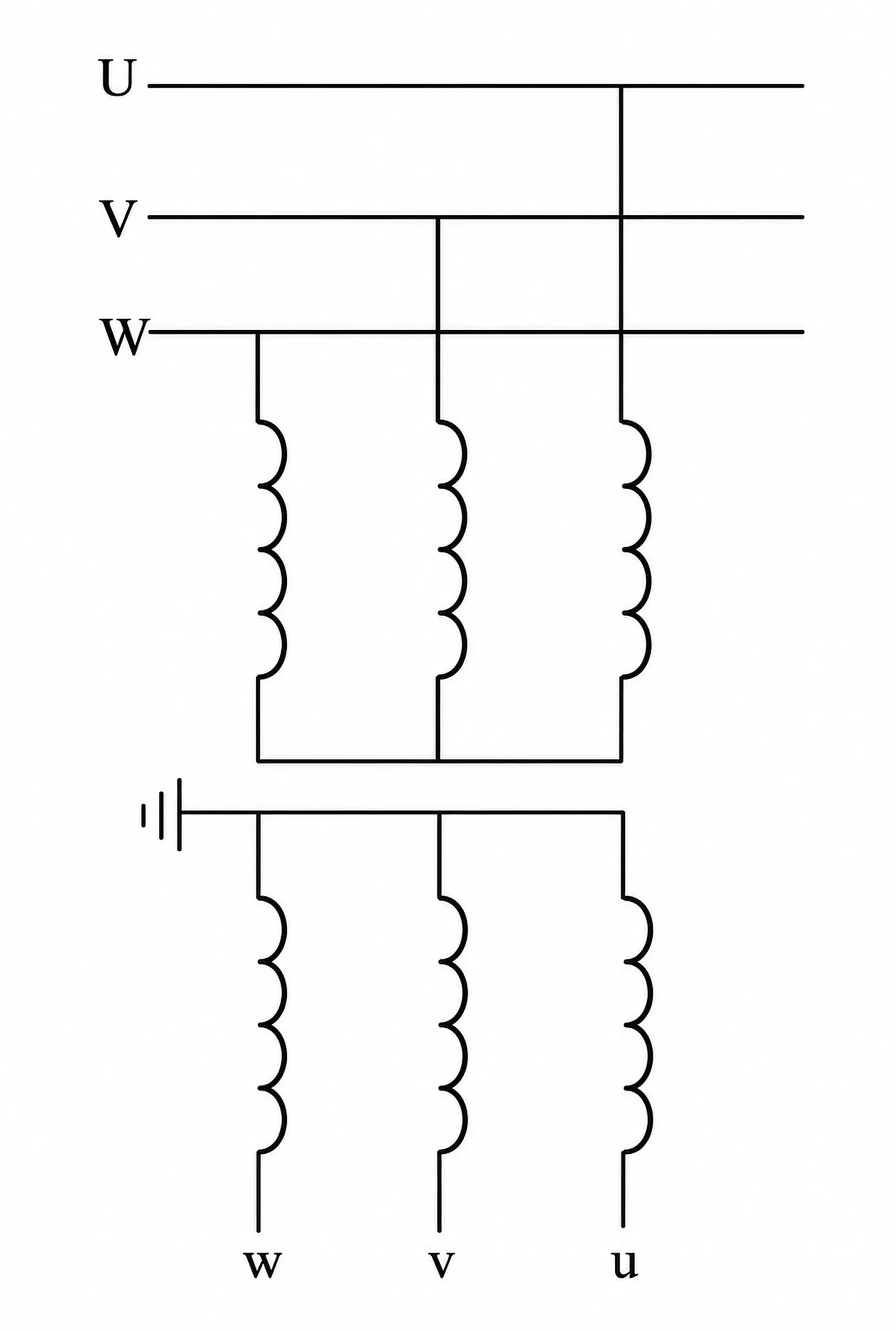
The figure illustrates the star connection configuration for a three-phase voltage transformer. Both the primary and secondary windings are connected in a star configuration; the primary neutral point is ungrounded, while the secondary neutral point is directly grounded. This connection method allows for the measurement of both phase-to-ground and phase-to-phase voltages and is suitable for 3–35 kV systems with low earth-fault currents.
Wiring of three-phase, five-limb voltage transformers
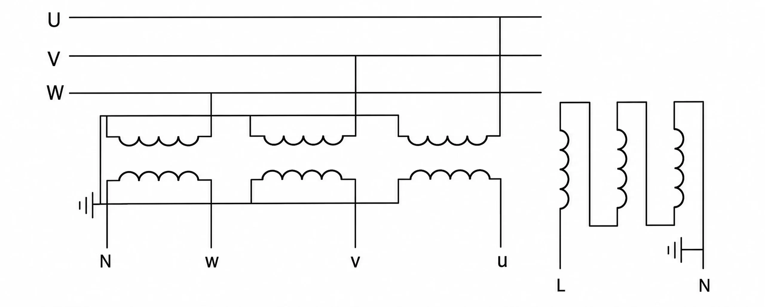
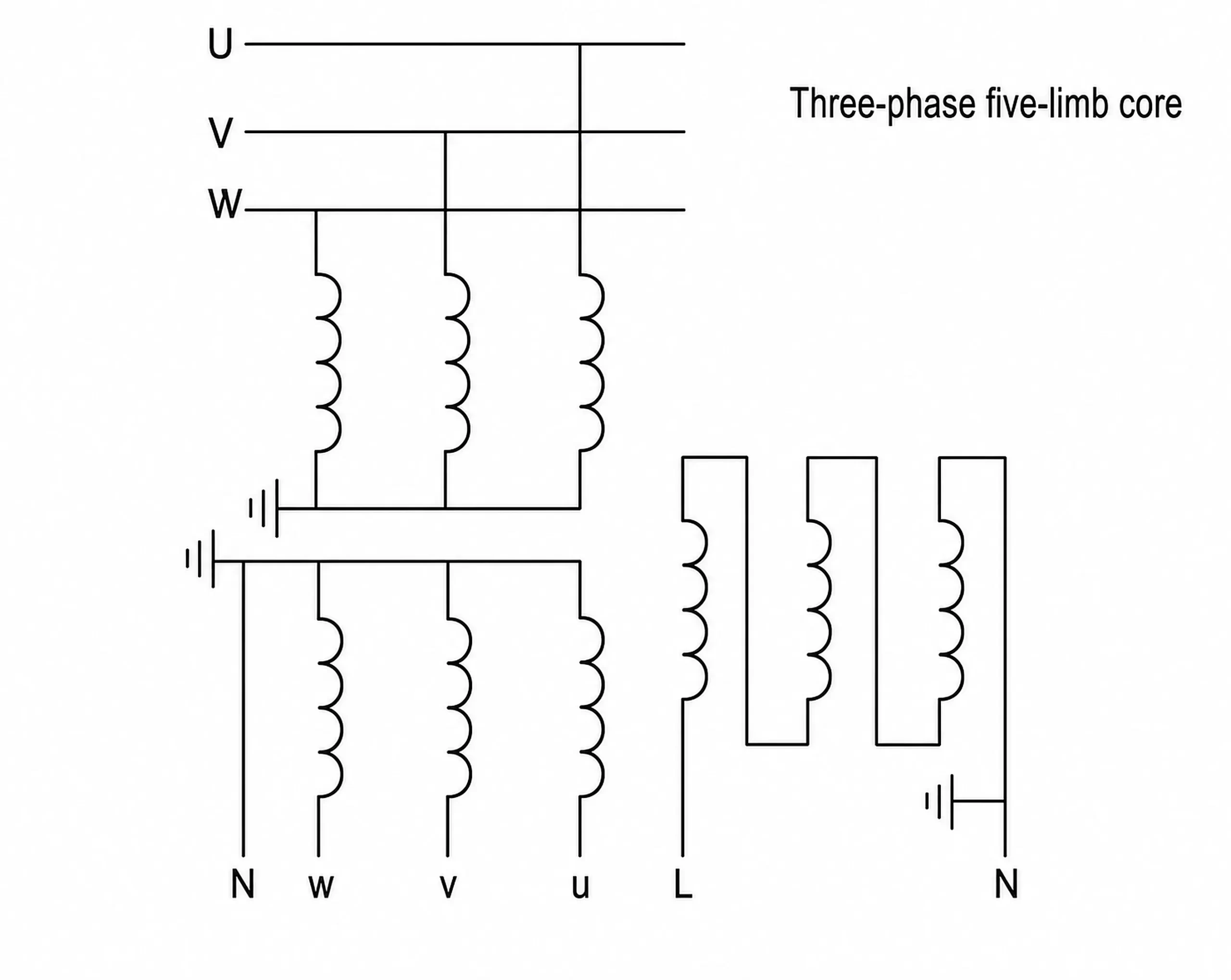
The figure shows the connection configuration for a three-phase, five-limb voltage transformer. The primary windings and main secondary windings are connected in a star configuration with the neutral point directly grounded, while the auxiliary secondary windings are connected in an open-delta configuration. This arrangement enables the measurement of line voltages, phase voltages, and zero-sequence voltages, and is widely used in power systems.
Conclusion
Different voltage transformer wiring configurations are suitable for different power system structures and measurement requirements. Proper selection and wiring are essential to ensure accurate voltage measurement, reliable protection, and safe system operation. Understanding the characteristics and applicable scenarios of each configuration helps ensure the correct configuration and reliable operation of voltage transformers.