A synchroscope is a key instrument used for generator synchronization, dual power transfer, and marine power systems. It compares the voltage, frequency, and phase angle between two AC power sources in real time to ensure safe synchronization before connection. This guide covers the basic wiring principles and typical wiring diagrams for 3-phase 3-wire, 3-phase 4-wire, generator-to-bus, generator-to-generator, dual power, and marine applications.
Two Standard Synchroscope Wiring Diagram
- Phase-to-Phase Wiring (Standard 3-Phase, 3-Wire / 3P3W Configuration)
Applicable Grid Conditions: Balanced three-phase, three-wire grids without a neutral wire: e.g., thermal power plant main transformers, energy storage stations, mobile generator trailers, traditional marine power systems, and the low-voltage side of oil-immersed transformers. Only three phase conductors (R/Y/B or L1/L2/L3) are present; there is no neutral (N) wire.
Wiring Layout Description:
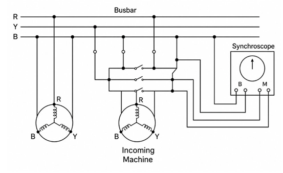
Left Side: Running Busbar/Generator, The R/Y/B three-phase busbars remain energized, serving as the system’s reference power source; two phases (R and B) are tapped directly and connected to the synchroscope’s “B” (Bus) terminal block.
Middle Section: Incoming Generator (Machine to be synchronized), The generator outputs three phases (R/Y/B) in a star configuration; the two phases corresponding exactly to the busbar phases (R and B) are selected and connected to the synchroscope’s “M” (Machine) terminal block. A synchronization circuit breaker is installed in the middle; closing it connects the two generators in parallel.
Right Side: Synchroscope Unit, The instrument features only four terminals (B1 and B2 for the busbar side; M1 and M2 for the generator side) and requires no neutral terminal; it simply acquires two sets of line voltages to compare phase and frequency.
- Phase-to-Neutral Connection (3-Phase, 4-Wire / 3P4W Configuration)
Applicable Grid Conditions: Civil or industrial power distribution systems with a neutral (N) conductor, supplying both three-phase power loads and single-phase 220V lighting/control loads; commonly found in data centers, factory low-voltage distribution rooms, and shore-to-ship power grid connection systems.
Wiring Layout Description:
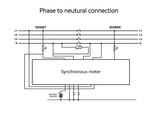
The power supply consists of two circuits: the generator set pending synchronization, (L1/L2/L3/N) and the mains busbar (L1/L2/L3/N); phase lines and the neutral line from both circuits are routed to the synchronoscope.
Voltage divider components (Vg) are connected in parallel at the input side of each phase line to match the instrument’s rated phase voltage input. The synchronoscope features two independent internal phase voltage acquisition circuits; the busbar L1+N and generator L1+N are connected to these respective inputs to measure the phase voltage difference.
Terminals for an auxiliary DC power supply (12/24VDC) are provided to power the digital synchronoscope’s LED indicators and synchronization relay output. A synchronization switch is connected in series within the three-phase circuit to enable the voltage signal input to the synchronoscope during the synchronization operation.
Specific Wiring Specifications for Three Typical Applications
Application one: Wiring for a Dual-Generator Parallel Synchronization Meter (G1/G2 Unit Switching)
Application: Automatic paralleling of two diesel generator sets of equal capacity and dual-source switching power stations; the units serve as mutual backups and are synchronized to the grid on a time-shared basis.
Wiring Layout Description:
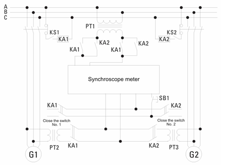
Voltage Acquisition Units: PT1 is the common busbar voltage transformer; PT2 and PT3 are dedicated to units G1 and G2, respectively; all provide a standard secondary output of 100V for synchronization.
Switching Relay Logic: KA1 is the synchronization selection relay for Unit 1, and KA2 is the synchronization selection relay for Unit 2. KS1 and KS2 are auxiliary contacts for the unit circuit breakers; the corresponding relay engages only after the unit’s circuit breaker closes, feeding that unit’s voltage into the synchronization meter.
Interlock Protection: The contacts of KA1 and KA2 are electrically interlocked to prevent both unit voltages from being connected to the synchronization meter simultaneously, thereby avoiding a short circuit between the two voltage sources.
Operation Switches SB1 & SB2: Manual synchronization selection buttons that trigger the synchronization circuits for G1 and G2, respectively, ensuring only one unit’s voltage is connected to the meter at a time.
The synchronization meter continuously monitors the common busbar voltage (PT1) as a reference and compares it against the voltages of G1 and G2 individually, enabling the two units to synchronize with the grid on a time-shared basis.
Application two: Generator-to-Grid Bus Synchronization (Standard Power Plant Configuration)
Application: Connection of generators from thermal, photovoltaic, or energy storage power plants to the public grid bus; standard synchronization wiring for large-scale onshore power plants.
Wiring Layout Description:
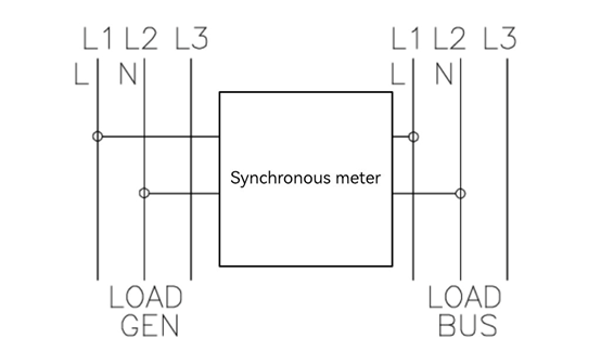
Left Side (GEN/Load Gen): Generator-side phases L and N are connected to the synchronoscope’s generator input terminals.
Right Side (BUS/Load Bus): External grid bus phases L and N are connected to the synchronoscope’s bus reference input terminals.
The two voltage circuits are completely independent with no electrical connection; synchronization parameter comparison is achieved via internal isolation windings within the instrument.
Paired with a synchronization protection relay; the closing circuit is interlocked if the synchronization angle, voltage difference, or frequency difference exceeds limits, thereby preventing erroneous operation.
Application three: Wiring for CSQ Series Marine-Specific Synchroscopes (DEIF Marine Standard)
Application: Three-phase, three-wire marine power systems for seagoing vessels and engineering ships; compliant with IEC 60092 marine electrical standards; utilizes the DEIF CSQ marine synchroscope solution.
Wiring Layout Description:
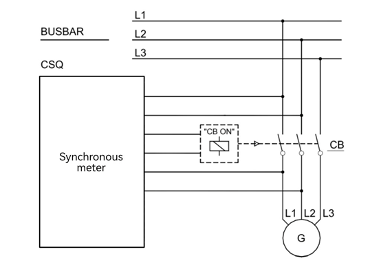
Upper Section (BUSBAR): Three-phase busbars (L1/L2/L3) from the ship’s main switchboard; two phases are tapped directly to connect to the synchroscope’s busbar reference circuit.
Lower Section (G): Three-phase output (L1/L2/L3) from the marine generator to be synchronized; the corresponding two phases connect to the generator circuit.
Main Circuit Breaker (CB) Auxiliary Contact (“CB ON”): The synchroscope’s voltage circuit is energized when the circuit breaker is open; once the circuit breaker closes, the auxiliary contact disconnects the synchroscope input to prevent power loss from the instrument remaining energized after grid connection.
Marine-Grade Requirements: Marine-grade flame-retardant shielded cables are used, with the shield grounded at one end to provide immunity against electromagnetic interference (EMI) from variable frequency drives (VFDs) and motors in the ship’s engine room.