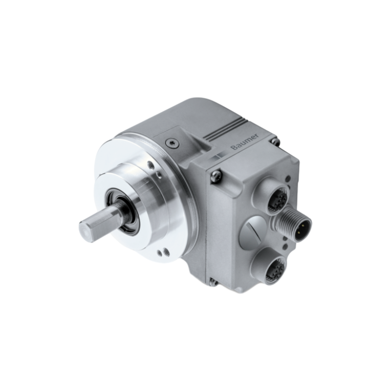
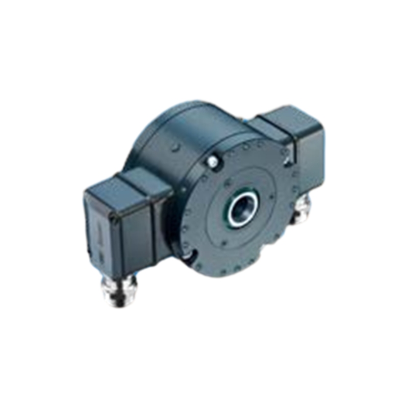
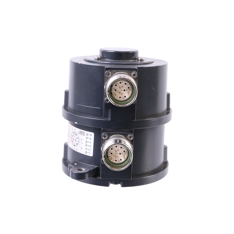
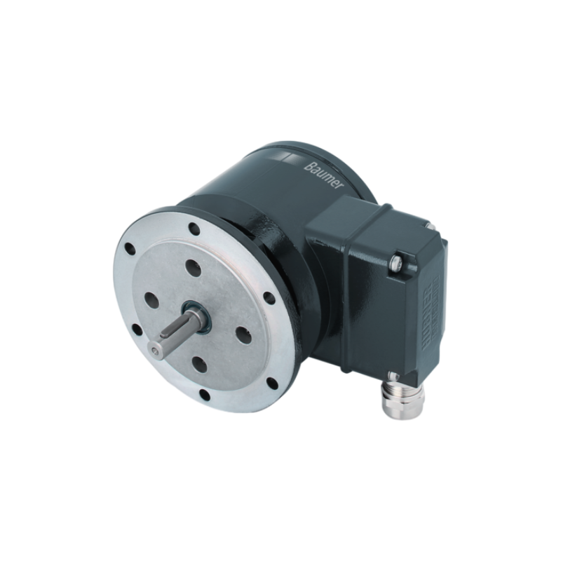
Features of Incremental Encoders HOG 10
- TTL output driver for cable length up to 550 m
- HTL output driver for cable length up to 350 m
- Very high resistance to shock and vibrations
- Hybrid bearing for extended service life
- Large terminal box, turn by 180° or axial terminal cover
Specifications of Incremental Encoders HOG 10
Voltage supply
- 9…30 VDC
- 5 VDC ±5 %
Consumption w/o load
- ≤100 mA
Pulses per revolution
- 300 … 5000
Phase shift
- 90 ° ±20°
Duty cycle
- 40…60 %
Reference signal
- Zero pulse, width 90°
Sensing method
- Optical
Output frequency
- ≤120 kHz
- ≤300 kHz (on request)
Output signals
- K1, K2, K0 + inverted
- Error output (option EMS)
Output stages
- HTL-P (power linedriver)
- TTL/RS422
Shaft insulation
- Suitable up to 2.8 kV
Transmission length
- ≤350 m at 100 kHz (HTL-P)
- ≤550 m at 100 kHz (TTL)
Interference immunity
- EN 61000-6-2
Emitted interference
- EN 61000-6-3
Approval
- CE
- UL approval / E217823
- Size (flange)
-
- ø105 mm
- Shaft type
-
- ø12…20 mm (blind hollow shaft)
- ø17 mm (cone shaft 1:10)
- Admitted shaft load
-
- ≤450 N axial
- ≤600 N radial
- Protection EN 60529
-
- IP 66
- Operating speed
-
- ≤6000 rpm (mechanical)
- Operating torque typ.
-
- 6 Ncm
- Rotor moment of inertia
-
- 340 gcm²
- Material
-
- Housing: aluminium die-cast
- Shaft: stainless steel
- Operating temperature
-
- -40…+100 °C
- -25…+100 °C (>3072 pulses)
- -50…+100 °C (optional)
- Resistance
-
- IEC 60068-2-6
- Vibration 20 g, 10-2000 Hz
- IEC 60068-2-27
- Shock 300 g, 6 ms
- Corrosion protection
-
- IEC 60068-2-52 Salt mist
- for ambient conditions C4 according to ISO 12944-2
- Explosion protection
-
- II 3 G Ex ec IIC T4 Gc (gas)
- II 3 D Ex tc IIIC T135°C Dc (dust)
- (only with option ATEX)
- Connection
-
- Terminal box
- Terminal cover
- 2x terminal box (with option M)
- Weight approx.
-
- 1.6 kg
- 1.8 kg (with option M)