You may know that the current transducer working principle is based on electromagnetic induction. To help you know it in detail, this article will introduce you to the working principle of a current transducer.
What is the current transducer?
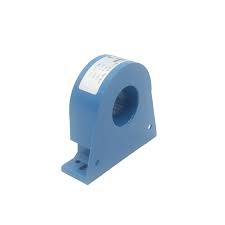
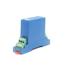
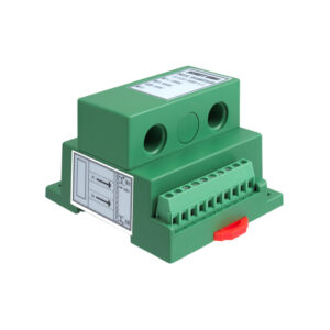
A current transducer is a device used to measure or monitor electrical current flowing through a conductor. It is commonly used in various applications, including power distribution, motor control, energy management, and industrial automation.
Current transducer working principle
You can clearly understand how a current transducer works from the following aspects:
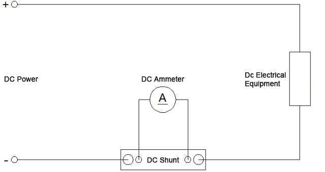
1. Primary Conductor: The current transducer is typically clamped around or inserted into the primary conductor, which is the wire or busbar through which the electrical current to be measured flows. The primary conductor carries the current of interest.
2. Magnetic Core: Inside the current transducer, there is a magnetic core, which is usually made of laminated iron or a ferrite material. The core’s primary purpose is to concentrate the magnetic field generated by the current flowing through the primary conductor.
3. Primary Winding: Wrapped around the magnetic core, there is a primary winding or coil. This coil is connected in series with the primary conductor. The current to be measured passes through this coil, generating a magnetic field in the core proportional to the primary current.
4. Secondary Winding: Around the same magnetic core but electrically isolated from the primary winding, there is a secondary winding or coil. This secondary winding is connected to the measuring or monitoring circuit. The magnetic field generated by the primary current induces a voltage in the secondary winding through electromagnetic induction.
5. Turns Ratio: The turn ratio between the primary and secondary windings determines the transformation ratio of the current transducer. For example, if the turns ratio is 1:100, a primary current of 100 amperes will induce a secondary current of 1 ampere (100 times smaller) or a proportional voltage.
6. Output Signal: The induced voltage or current in the secondary winding is a scaled-down replica of the primary current. This output signal is linearly proportional to the primary current and follows the same waveform. In AC applications, the output signal is AC as well, while in DC applications, it remains DC.
7. Isolation and Signal Conditioning: In many cases, the secondary circuit is electrically isolated from the primary circuit for safety and to prevent interference. Additionally, the output signal may undergo signal conditioning, such as amplification, filtering, or analog-to-digital conversion, to match the requirements of the measurement or control system.
8. Measurement or Control: The conditioned output signal is then sent to measurement instruments, data acquisition systems, control devices, or microcontrollers. These systems can accurately measure and display the current value or use it for various control and monitoring purposes, such as overcurrent protection, energy metering, or feedback control in industrial processes.
In summary, a current transducer operates based on the principle of electromagnetic induction. It uses a magnetic core and two coils (primary and secondary) to transform the primary current into a secondary voltage or current that is proportional to the primary current. This secondary signal is isolated, conditioned, and then used for measurement, monitoring, or control in a wide range of electrical and electronic applications.