Abstract: This article will introduce the IP transducer working principle from dentition, working principle, and components.
What is an I/P transducer?
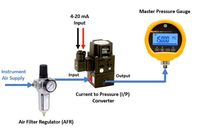
An I/P transducer is a device used to convert one form of energy into another form. When used in control systems, it is used to convert one form of signal into another. Electrical I/P converters convert analog signals into pneumatic signals. Its function is to convert the analog output of the controller into a proportional pneumatic value to control the actuators in the system. The actuator is the final control element.
Typically, the current input signal to the pressure sensor is in the 4-20mA range, and the proportional pneumatic output value is in the 3-15psi range.
I/P transducer working principle
The current flow to the pressure sensor is based on the principle of electromagnetic force balance. There is a coil in the system, and when the current signal flows from the controller to the coil, a force is generated between the coil and the baffle.
How does an electro-pneumatic transducer work?
The main elements of an electrical converter are the coil, baffle, and nozzle. One end of the bezel pivots and the other end is free so there is some flexibility in moving up and down, and magnetic material is attached to the free end of the bezel. Coils are present in the system to act as electromagnets. When current is input from the controller into the system and passes through the coil, a magnetic field is generated. The electromagnet tends to attract the magnetic material attached to the free end of the baffle. This causes the baffle to move downward toward the coil. The stronger the current flowing through the coil, the stronger the attraction between the coil and the magnetic material.
There is a nozzle near the baffle. There is some gap between the nozzle and the baffle. Air flows through the nozzle. Maintain a standard supply of approximately 20 psi as supply pressure. If the nozzle is capped and the air is not allowed to pass through, all 20psi of pressure will come out the other end of the nozzle. If the nozzle is not fully covered, the pressure output from the other end of the nozzle will be less than 20 psi.
The size of the gap between the nozzle and baffle depends on the amount of current flowing through the coil. If a large current flows through the coil, a strong attraction will be generated between the coil and the magnetic material, so the baffle will be pulled downward, and when the baffle moves downward, the gap between the nozzle and the baffle will decrease. A smaller gap means less air will pass through the nozzle end, so most of the supply pressure air will move out of the end opposite the nozzle. If a weak current passes through the coil, the gap between the nozzle and the baffle will increase, and more air will pass through the nozzle end.
The system is set up in such a way that if 4mA flows through the coil, the pressure on the end opposite the nozzle is 3psi. If 20 mA flows through the coil, the pressure at the end opposite the nozzle is 15 psi. They follow a proportional linear relationship, so all intermediate pressure values are equal to 0.75 times the current value. Therefore, if the current value is 6mA, the pressure value is 0.75*6=4.5psi.
Why is 4-20mA the main industry standard for I/P transducers?
The 4-20mA current loop is ideal for transmitting signals over long distances. They use less wiring than similar systems and are very simple to connect, configure, and troubleshoot. Another important reason is that low current means safe operation. This is particularly useful near areas where there are vapors or dust around, as the low power consumption means there is no danger of reaching a situation where the vapor or dust could burn.