The Multifunction Meter Connection Diagram is also called the MFM meter wiring diagram. To help you install and connect the multi-function meter correctly, this article will introduce in detail the connection diagram of the multifunction electric meter and its related points.
Components of multifunction meter connection diagram
The basic components of a multi-function meter connection diagram usually include the following main elements:
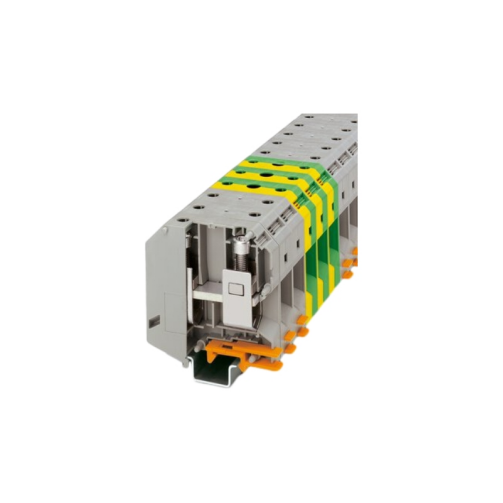
Power interface: It is used to connect the meter to the power line. This is usually a terminal block or socket that connects the power supply to the meter.
Current interface: It is used to connect current sensors (such as current transformers) to measure current. Typically, a terminal block or socket for connecting the output of a current sensor.
Voltage interface: It is used to connect voltage sensors (such as voltage transformers) to measure voltage. Typically, a terminal block or socket connects the output of a voltage sensor.
Display: It is used to display various parameters measured by the meter, such as current, voltage, power, energy, etc.
Communication interface: It is used to communicate with external systems or devices, such as SCADA systems, BMS systems, or computers. Usually, it can be a serial port (such as RS-485), Ethernet interface, or wireless communication interface.
Function button: used to set the parameters and functions of the meter, such as switching display modes, resetting energy consumption accumulation, etc.
Relay output: An output interface used to trigger alarms, control other devices, or perform other operations.
Protection device: Some multi-function meters may also integrate overload protection, short-circuit protection, and other functions to protect the safe operation of the meter and related equipment.
The above are the general components of the multi-function electric meter connection diagram. The specific electric meter connection diagram may vary according to different models, manufacturers, or application requirements.
Precautions for multifunction meter wiring diagram
Electrical parameter matching: Ensure that the rated current and rated voltage of the selected multi-function meter match the requirements of the electrical system. In addition, parameters such as the number of phases (single-phase, three-phase) and frequency of the electrical system also need to be considered.
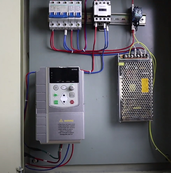
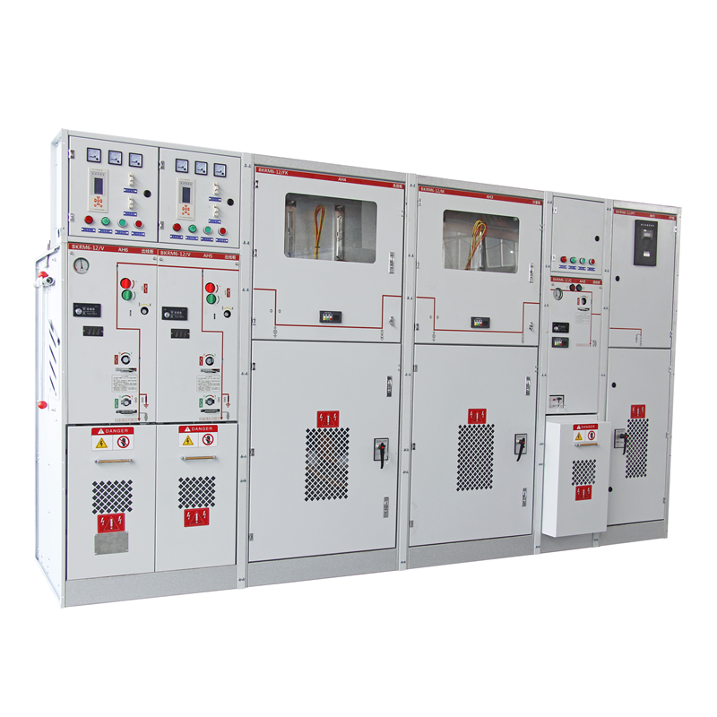
Installation location: Choose an appropriate installation location to ensure that the meter can accurately measure current and voltage and is easy to observe and maintain. Normally, the meter should be installed in the main circuit of the electrical system to avoid installation in overloaded, humid, or high-temperature environments.
Sensor installation: Where and how current and voltage sensors are installed is critical to the accuracy of the measurements. Make sure the sensor is installed in the proper location and the connections are correct and secure to avoid errors or interference.
Correctness of wiring: Ensure that each wiring of the meter is correctly connected to the electrical system, including power wiring, current wiring, voltage wiring, etc. Wiring errors can result in inaccurate measurements or damage to the meter.
Communication settings: If the multi-function meter supports communication functions, the communication parameters need to be set correctly and connected to external systems or devices to achieve functions such as data collection, monitoring, and control.
Calibration and debugging: After installation, calibration and debugging should be performed to ensure the measurement accuracy and stability of the meter. This includes verifying the consistency of measurements with actual electrical parameters and making necessary adjustments.
Safety considerations: Relevant safety regulations and operating procedures must be followed during the installation process to ensure a safe and reliable installation process and avoid accidents.
To summarize, the key factors to consider when connecting a multifunction meter involve matching electrical parameters, mounting location, sensor installation, wiring correctness, communication settings, calibration and commissioning, and safety considerations. Correct connections and settings ensure that the meter can accurately and stably measure electrical parameters and provide reliable data support for the monitoring and management of electrical systems.
Some examples of Multifunction meter connection diagram:
1. MFM376 Selec Multifunction Meter connection diagram
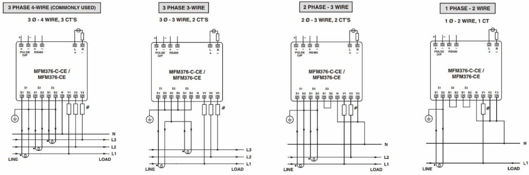
MFM meter wiring diagram of selec multifunction meter
The Selec Multifunction Meter MFM376 is a multi-purpose LED meter that works with 1-phase 2-wire, 3-phase 3-wire, and 3-phase 4-wire systems. Voltage levels between 11 and 300V (L-N) and 19 and 519V (L-L) can be measured by it.
2. Blue Jay 194Q Multifunction Meter Connection Diagram
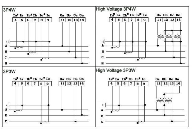
The 194Q Multifunction Meter can use for 3P3W or 3P4W LV installations. The 194Q multi-function power meter also has a digital RS485 communication port that uses the Modbus Protocol to transmit monitored data.
3. Rishabh RISH 3440 Multifunction Meter connection diagram
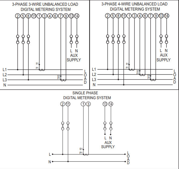
Rishabh Multifunction Meter RISH 3440 can program on-site the network connection as either 3 Phase 3 Wire or 4 Wire locally via front panel keys by entering into Programming mode or remotely via MODBUS (RS485). For single-phase applications, a single-phase version is available.
Multi-function meter connection errors and their troubleshooting methods
Common multifunction meter connection errors and their troubleshooting methods include:
Wiring errors: Wiring errors can cause the current or voltage sensor to be connected incorrectly or in the wrong location. This can cause the meter to fail to accurately measure current and voltage.
Troubleshooting method: Carefully check the wiring of the electric meter and ensure that the current sensor and voltage sensor are correctly connected to the corresponding terminals. Follow the installation instructions or wiring diagram of the electric meter for correct wiring.
Incorrect sensor installation position: Incorrect installation position of current sensors and voltage sensors can lead to measurement errors or interference.
Troubleshooting method: Reinstall the sensors, making sure they are installed in the appropriate location in the electrical system and well connected to the circuit under test. Avoid installing the sensor in an environment with humidity, high temperature or external interference.
Grounding Issues: Poor grounding of your meter can cause interference or misoperation in the electrical system.
Troubleshooting method: Ensure that the ground connection of the meter is good and meets the grounding requirements of the electrical system. Check and clean the grounding point and make sure the grounding conductor connection is tight and secure.
Communication failure: If the multi-function meter has a communication function, communication failure may cause the data collection or monitoring function to fail.
Troubleshooting method: Check whether the communication lines and connections are correct, and ensure that the communication interface settings are correct and match the communication parameters of the external system or device. Reset the communication parameters and check the status of the communication device.
Wrong parameter settings: Wrong parameter settings of a multi-function meter may result in inaccurate measurements or failure to function properly.
Troubleshooting method: Check the parameter settings of the electric meter to ensure that each parameter setting is correct and adjust it as needed. Reset the parameters of the meter and make sure they match the actual parameters of the electrical system.
Equipment failure: If the above methods cannot solve the problem, the multifunction meter itself may be faulty or damaged.
Troubleshooting method: Contact the supplier or manufacturer for repair or replacement. If it is within the warranty period, you can apply for repair or replacement service.
To sum up, common multi-function meter connection errors may involve wiring errors, wrong sensor installation locations, grounding problems, communication failures, wrong parameter settings or equipment failures, etc. Through careful inspection and troubleshooting, these issues can be resolved and ensure the multifunction meter is functioning properly and accurately measuring electrical parameters.
By correctly connecting multi-function meters, you can ensure their normal operation in the power system and provide accurate measurement and monitoring functions, thereby helping to achieve safe, stable and efficient operation of the power system.