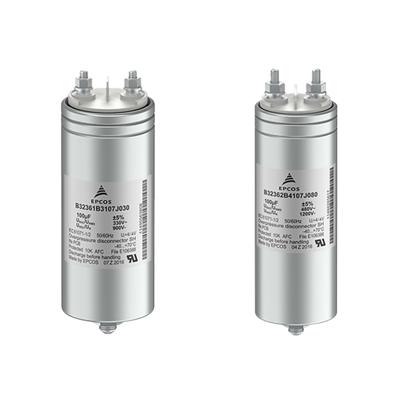
Features
- Robust design thanks to aluminum can and top
- Compact dimensions
- Integrated overpressure disconnection safety device
Application
- Frequency converters
- Inverter based home appliances
- Solar inverters
- Variable speed motor drives
Specification
| Operating temperature range | Max. operating temperature, THot Spot, max
Upper category temperature Tmax. Lower category temperature Tmin. |
+105 ºC
+85 ºC -40 ºC |
|||
| Insulation Resistance RINS, given as
time constant t = CR • RINS, rel. humidity ≤65% (minimum as-delivered values) |
t >10 000 s (after 1 min)
For VR ≥500 V measured at 500 V For VR <500 V measured at VR |
||||
| DC voltage test between terminals (10 s) | 1.5 • VR | ||||
| Voltage test terminal to case (10 s) | 2110 V | AC, 50Hz | |||
| Reliability: | Failure rate l | 75 fit (≤1 • 10-9) at 0.5 • VR, 40 ºC | |||
| For conversion to other operating conditions and | |||||
| temperatures, refer to chapter “Quality, 2 Reliability” | |||||
| Service life tSL | 100 000 h at VR, 70 ºC | ||||
| VR (DC) | 450 V | 800 V | 1100 V | 1300 V | |
| Continuous operation voltage (Vop) at Top of 85 ºC | 450 V | 800 V | 1100 V | 1300 V | |
| For temperatures between 85 ºC and 105 ºC | 2.5% / ºC of Vop derating compared to Vop at 85 ºC | ||||
| Test | Reference | Conditions of test | Performance requirements | |
| Electrical parameters (Routine test) | IEC61071: 2007 | Voltage between terminals,
1.5 VR, during 10 s Insulation resistance, RINS at VR if VR <500 V or 500 V if VR ≥500 V |
Within specified limits | |
| Capacitance, C at 1 kHz | ||||
| (room temperature) | ||||
| Dissipation factor, tan d at 1/10 kHz | ||||
| (room temperature) | ||||
| Robustness of terminations (Type test) | IEC 60068-2-21: 2006 | Tensile strength (test Ua1) | Capacitance and tan d
within specified limits |
|
| Wire diameter | Tensile force | |||
| 0.8 <d1 ≤1.25 mm
>1.25 mm |
20 N
40 N |
|||
| Resistance to soldering heat (Type test) | IEC 60068-2-20: 2008,
test Tb, method 1A |
Solder bath temperature at 260 ±5 °C, immersion for 10 seconds | |∆C/C0| ≤2%
|∆tan d| ≤0.002 RINS ≥50% of initial limit Mechanical: |
|
| No visible damage | ||||
| Rapid change of temperature
(Type test) |
IEC 61071: 2007 | TA = lower category temperature TB = upper category temperature Five cycles, duration t = 30 min | |∆C/C0| ≤2%
|∆tan d| ≤0.002 RINS ≥50% of initial limit Mechanical: |
|
| No visible damage | ||||
| Vibration and shocks
(Type test) |
IEC 61071: 2007 | In accordance with IEC 60068-2-6 f = 10 Hz to 55 Hz a = ±0.35 mm
Test duration per axis = 10 frequency cycles (3 axes offset from each other by 90°), 1 octave/min. |
Electrical:
|∆C/C0| ≤0.5% at 1 kHz
Mechanical: No visible damage |
|
| Mounting conditions: | ||||
| The leads shall fix the capacitor and the body must be properly clamped. | ||||
| Climatic sequence (Type test) | IEC 60384-16: 2005 | Dry heat Tb / 16 h
Damp heat cyclic, 1st cycle +55 °C / 24 h / 95% … 100% RH Cold Ta / 2 h Damp heat cyclic, 5 cycles |
No visible damage
|∆C/C0| ≤3% |∆tan d| ≤0.001 RINS ≥ 50% of initial limit |
|
| +55 °C / 24h / 95% … 100% RH | ||||
| Test | Reference | Conditions of test | Performance requirements |
| Damp heat | IEC 60384-16: 2005 | Test Ca | No visible damage |
| Steady state | 40 °C / 93% RH / 56 days | |∆C/C0| ≤5% | |
| (Type test) | I∆tan d| ≤0.005 | ||
| RINS ≥50% of initial limit | |||
| Endurance (Type test) | IEC 61071: 2007 | +85 °C / 1.3 VR / 500 hours and
1000 discharges at 1.4 IR and +85 °C / 1.3 VR / 500 hours |
No visible damage
|∆C/C0| ≤3% |∆tan d| 0.015 (10 kHz) |
| RINS ≥50% of initial limit | |||
| Mechanical: | |||
| No visible damage |