Power transducer working principle is generally converting various forms of electrical signals into standardized, measurable outputs that can be easily interpreted by monitoring and control systems. This article will introduce the working principle of power transducer from different transducer types.
1. Voltage Transducer Working Principle
A voltage transducer is designed to measure the electrical potential difference between two points in a circuit and convert it into a proportional analog or digital signal. The working principle revolves around the use of a voltage divider, typically comprising resistors, to scale down high voltages to safer, measurable levels.
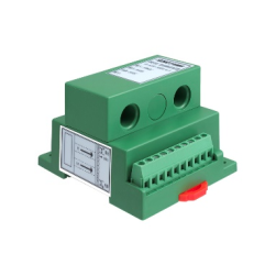
The transducer first samples the input voltage, which may be either AC or DC. This sampled voltage is then fed into a signal conditioning circuit, where it is often filtered, amplified, or attenuated to match the input range of the transducer’s output stage. The processed signal is then converted into a standardized output, such as 0-5V, 4-20mA, or a digital output in some cases. This output can be easily read by meters, data acquisition systems, or control systems, enabling real-time monitoring and analysis of the voltage in the circuit.
2. Current Transducer Working Principle
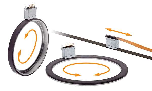
Current transducers operate on the principle of converting the current flowing through a conductor into a corresponding electrical signal. This is typically achieved through the use of magnetic field sensing components like Hall effect sensors, current transformers, or Rogowski coils, depending on whether the current is AC or DC.
For AC currents, a current transformer is commonly used. It consists of a primary winding, through which the measured current flows, and a secondary winding, where an induced current proportional to the primary current is generated due to electromagnetic induction. This secondary current is then conditioned and converted into a standardized output signal.
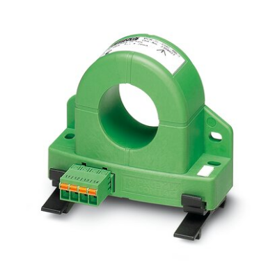
In the case of DC currents, Hall effect sensors are more appropriate. These sensors detect the magnetic field generated by the current flowing through the conductor. The strength of the magnetic field is proportional to the current, and the Hall sensor converts this field into a voltage signal, which is then processed and output as a standardized current or voltage signal.
3. Power Transducer Working Principle
A power transducer integrates the functions of both voltage and current transducers to measure electrical power—whether active (real), reactive, or apparent. The working principle of a power transducer involves simultaneous measurement of the voltage across and the current through a load.
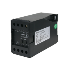
Firstly, the transducer samples the voltage and current signals from the electrical circuit. These signals are processed separately by the voltage and current measurement modules. The voltage signal is conditioned as described in the voltage transducer principle, and the current signal is conditioned following the current transducer principle.
The processed voltage and current signals are then multiplied together to calculate the instantaneous power. Depending on the type of power being measured, further mathematical operations may be performed. For instance, to obtain real power (measured in watts), the instantaneous power is integrated over time. To measure reactive power (in VARs), the voltage and current signals are phase-shifted by 90 degrees before multiplication.
The final output is a signal proportional to the power, which can be either an analog signal (e.g., 4-20mA) or a digital signal, making it suitable for real-time monitoring and control in various applications, such as in power quality monitoring, energy management systems, or industrial automation.
4. Frequency Transducer Working Principle
Frequency transducers are specialized devices designed to measure the frequency of an electrical signal, typically within a power system, and convert it into a standardized output. The working principle relies on detecting the zero-crossings of the AC signal, which occur at regular intervals corresponding to the signal’s frequency.
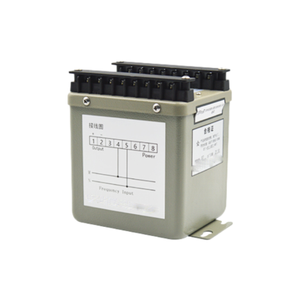
The transducer first captures the AC signal and processes it through a zero-crossing detector circuit. This circuit generates pulses every time the signal crosses the zero-voltage level, effectively converting the waveform’s frequency into a pulse rate. The pulse rate is directly proportional to the frequency of the input signal.
These pulses are then counted over a specific time period, usually a fraction of a second, to determine the frequency. The transducer then converts this frequency data into a proportional output signal. Like other transducers, the output may be in the form of a current, voltage, or digital signal, depending on the application.
Conclusion
Power transducers, by integrating the principles of voltage, current, and frequency transducers, provide a comprehensive solution for monitoring and managing electrical power. Understanding these individual transducer principles helps in appreciating the complex yet efficient operation of power transducers, which are vital for maintaining the stability, efficiency, and safety of modern electrical systems.